after my midterm-log, and doing the serial labs, i realised that the beauty of this course for me lied in the electricity. again:
we frequently interact with electricity, but its magic is too quick to comprehend. there is a lot that we still don’t understand, but that doesn’t stop us from consuming 24,398,000,000,000,000 watt-hours of electrical-energy every year.
this time, instead of seeing the things we can’t, i wanted to focus on hearing the things we can’t (electrically). as i did my midterm reflection, i also realised that i wanted to make something that produces immediate feedback, and that feedback is unexpected.
so, for my final project (see original attempt at final-project-1_log), i want to build a portable, hackable synthesizer, without a microcontroller, that simply uses electricity to generate sound (that i could then orchestrate musically).
output:
But on the other hand, if you think about the “laptop music” style of performance which is currently in vogue, you might notice that there could be a problem, even if the music sounds good, with watching a person sitting in front of a computer and operating the mouse and keyboard. It is just too depressingly similar to what hundreds of millions of workers have to do from nine to five at the office.
When evening comes and we go to the concert, we might like to experience something different, something visceral, something that is a direct result of muscular energy. We might like the relief of something zany and crazy.
As Antonin Artaud said, there are plenty of people in the real world with two arms and two legs; in the theater we would like to see creatures with three.
ethos:
every time i open this page to update, i want to remind myself this:
the point of this project is to experiment, and to further my understanding of how electricity moves (and produces sound).
251109:
prisha responded to my request of 555-timer-ics, after david rios’s recommendations of using them. she shared the book: handmade electronic music, by nicolas collins.
i tried wrapping my head around 555-timer-ics, but it was too complicated to understand. so, i began with the book; and made a speaker pulsate first.
i then made this, a 555 metronome (via this tutorial):
if i reversed the polarity of the speaker, this is produced:
scratching:
photoresistor instead of a 0.01-uf capacitor.
251113:
i realised that my main tool was the 555-timer-ic (even though other fancier chips exist). i decided to spend some time understanding it.
david rios shared this video: https://www.youtube.com/watch?v=ABWU7FlM1T0
these are my notes:
- can be used as a timer, oscillator, or flip-flop.
- monolithic timing circuit.
- drive ttl logic (logic-gates).
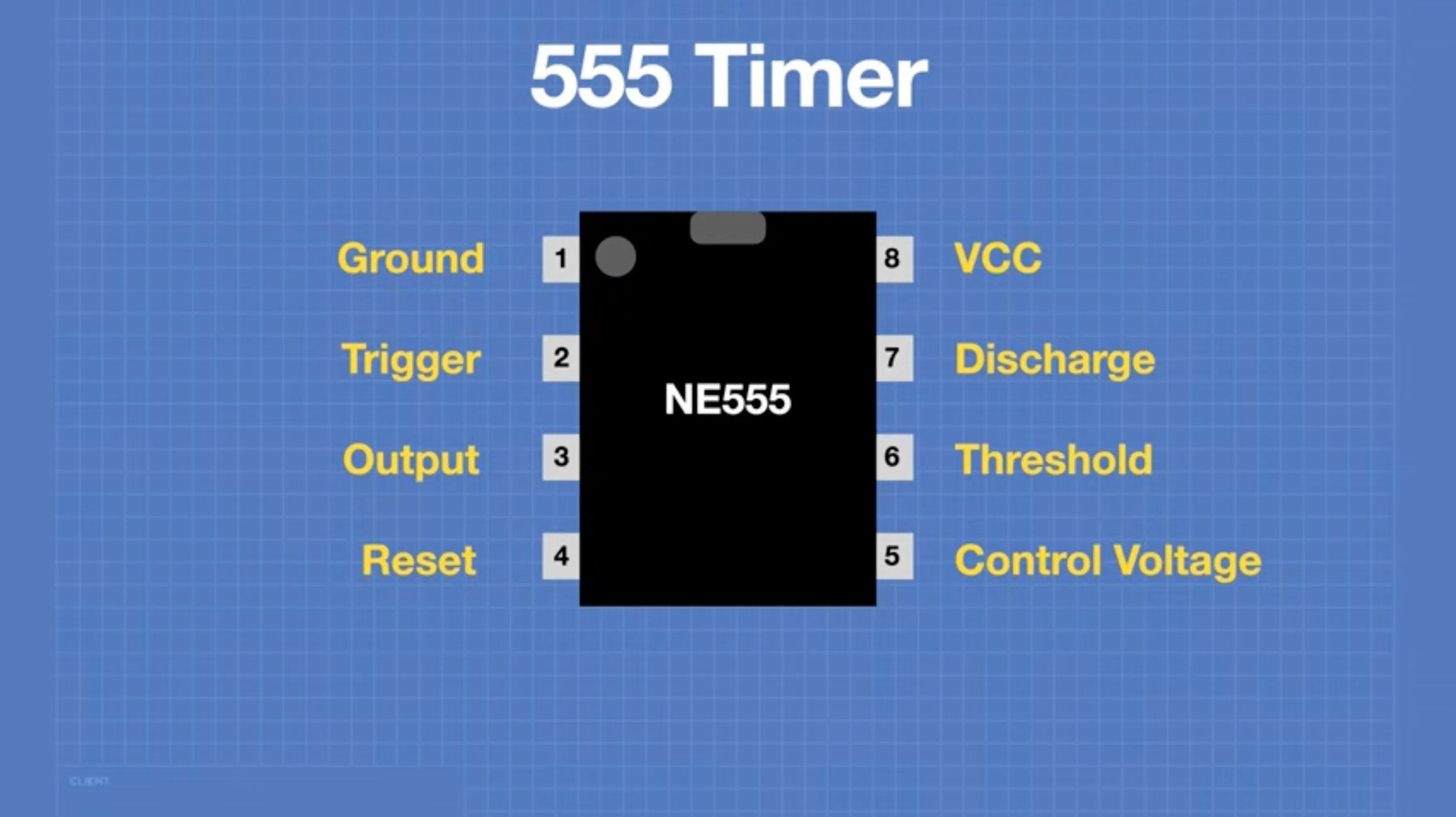
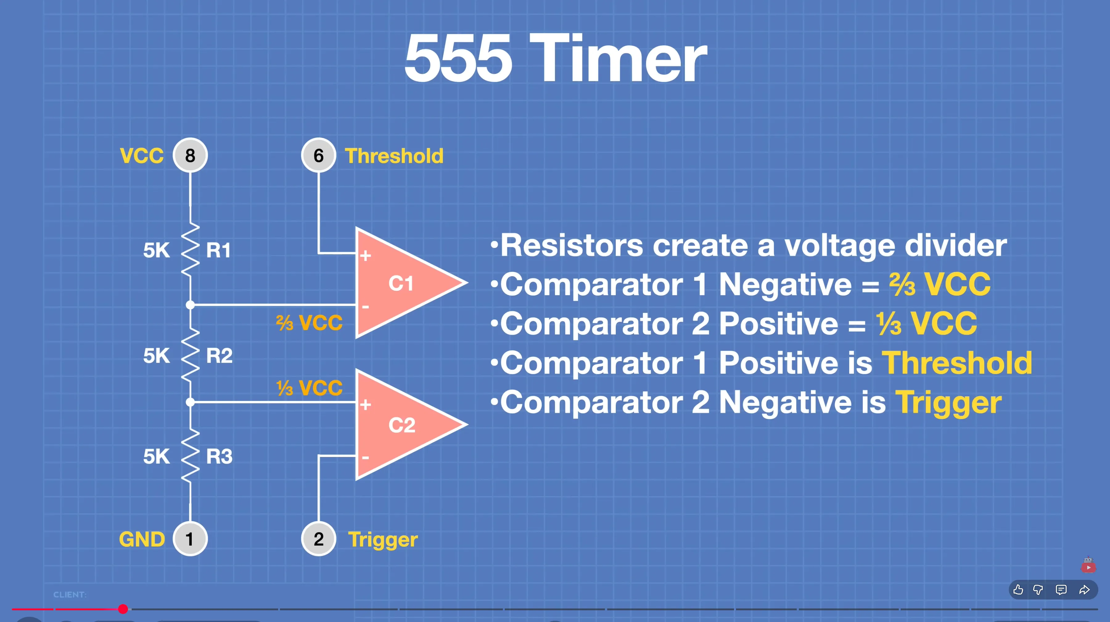
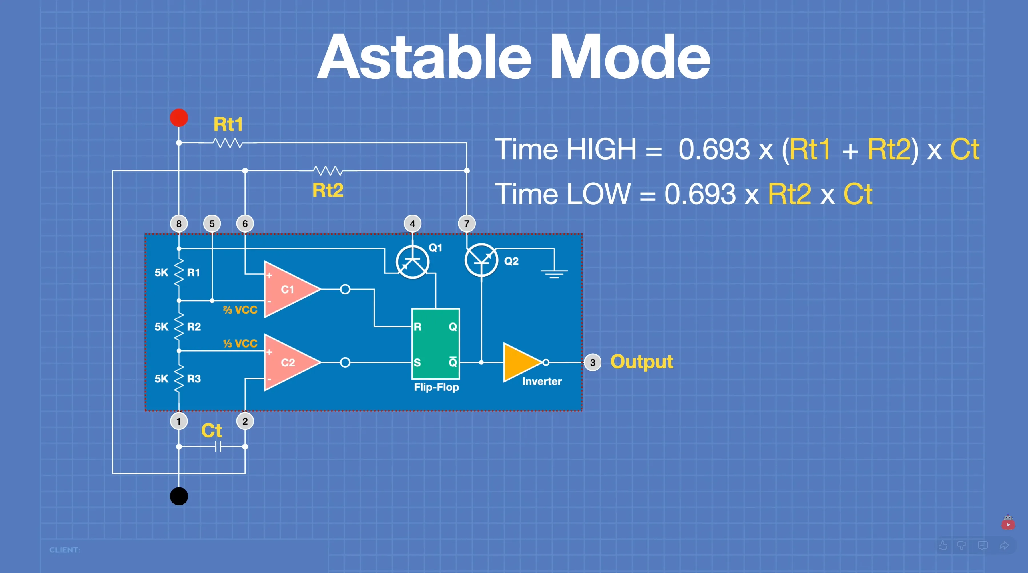
inside the ic, 3 resistors create a voltage-divide. two comparators compare voltage across the positive & negative end of themselves, and output a digital signal of high & low.
basically, by changing threshold & trigger, i can change what is sent out (high or low).
but these are then inverted and sent to a flip-flop. i don’t know why they’re inverted, but ok.
the s/r flip flip has two inputs:
s(et) and r(eset), and output is q or !q.
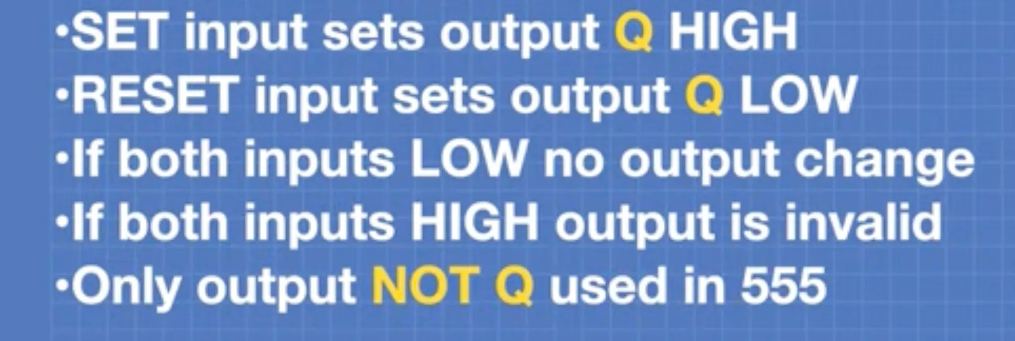
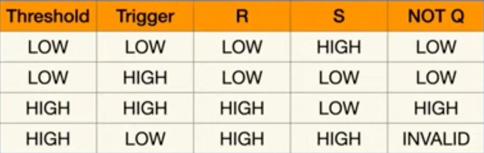
!q is fed through an inverter, meaning that the !q output actually results in q output when going out from pin-3.
control-pin on pin-5 connects directly to comparator negative. so, basically, the comparator voltage does not need to be 2/3rds of vcc all the time.
if reset is set to off, the flip-flop turns off and resets the timer.
value of capacitor connection on discharge pin can be used to set value of timing on the 555.
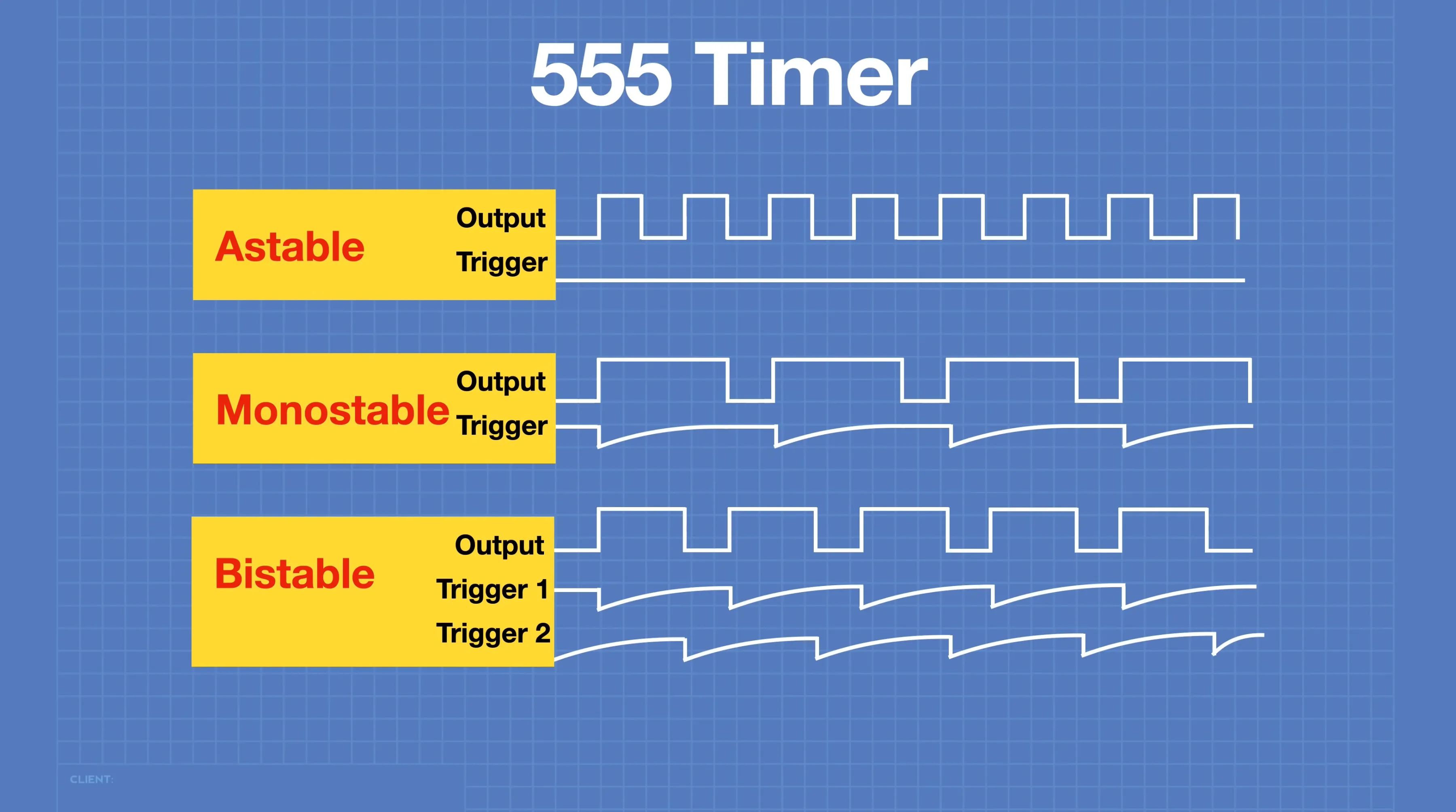
modes of the 555 (control output pulses via triggers):
25114:
i watched a lot of videos to understand the 555-timer. struggled. i need to understand it to be able to extract the most from it.
i made many, many circuits, and used the oscilloscope. nothing was substantial. then, i found this tutorial: https://www.youtube.com/watch?v=7PxkpQSsJ3E
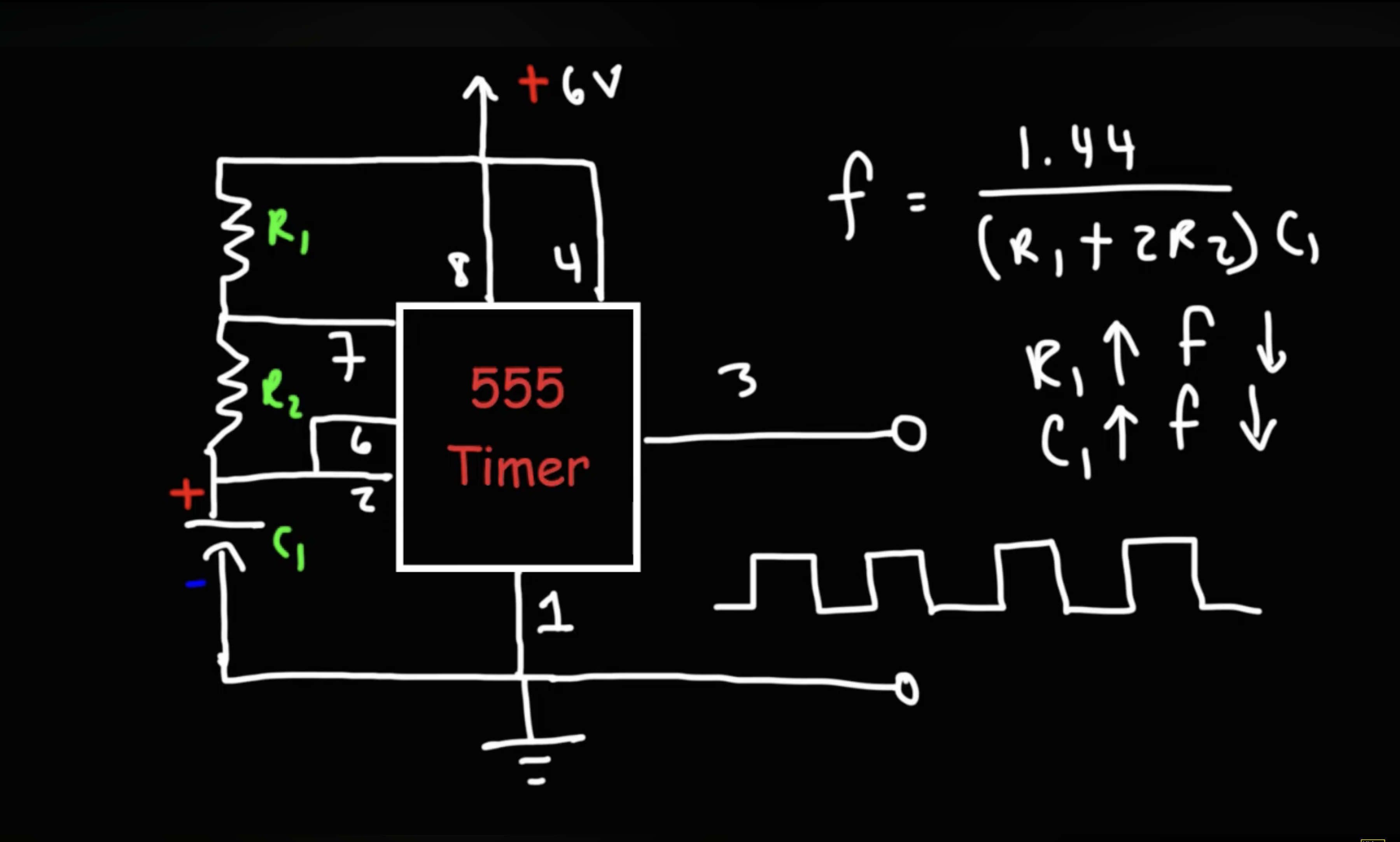
i understood how to make a voltage controlled oscillator using voltage dividers.
high-frequency pitch bender:
i can use this to change pitch by adding a fsr between the resistors. circuit for the future:
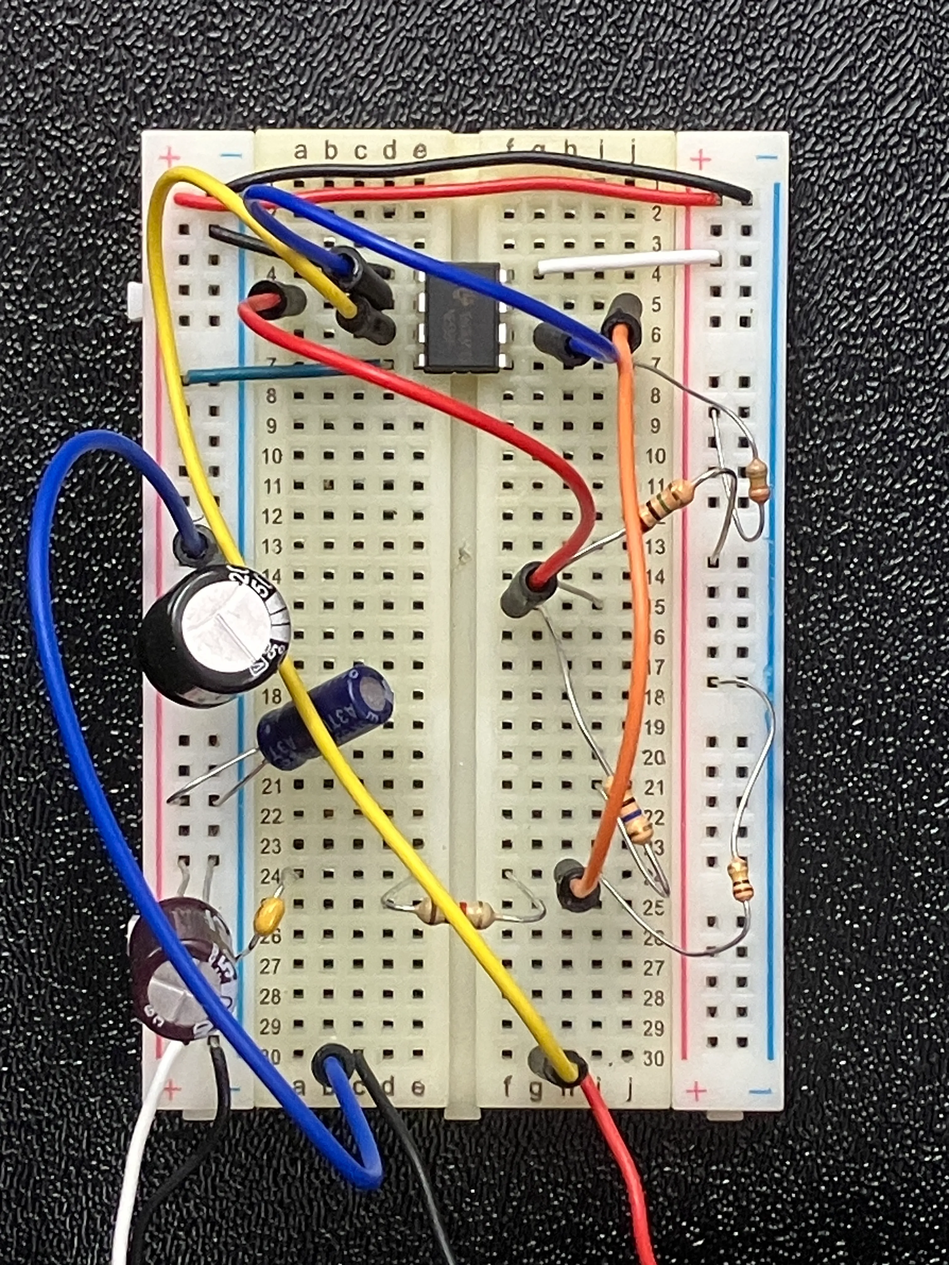
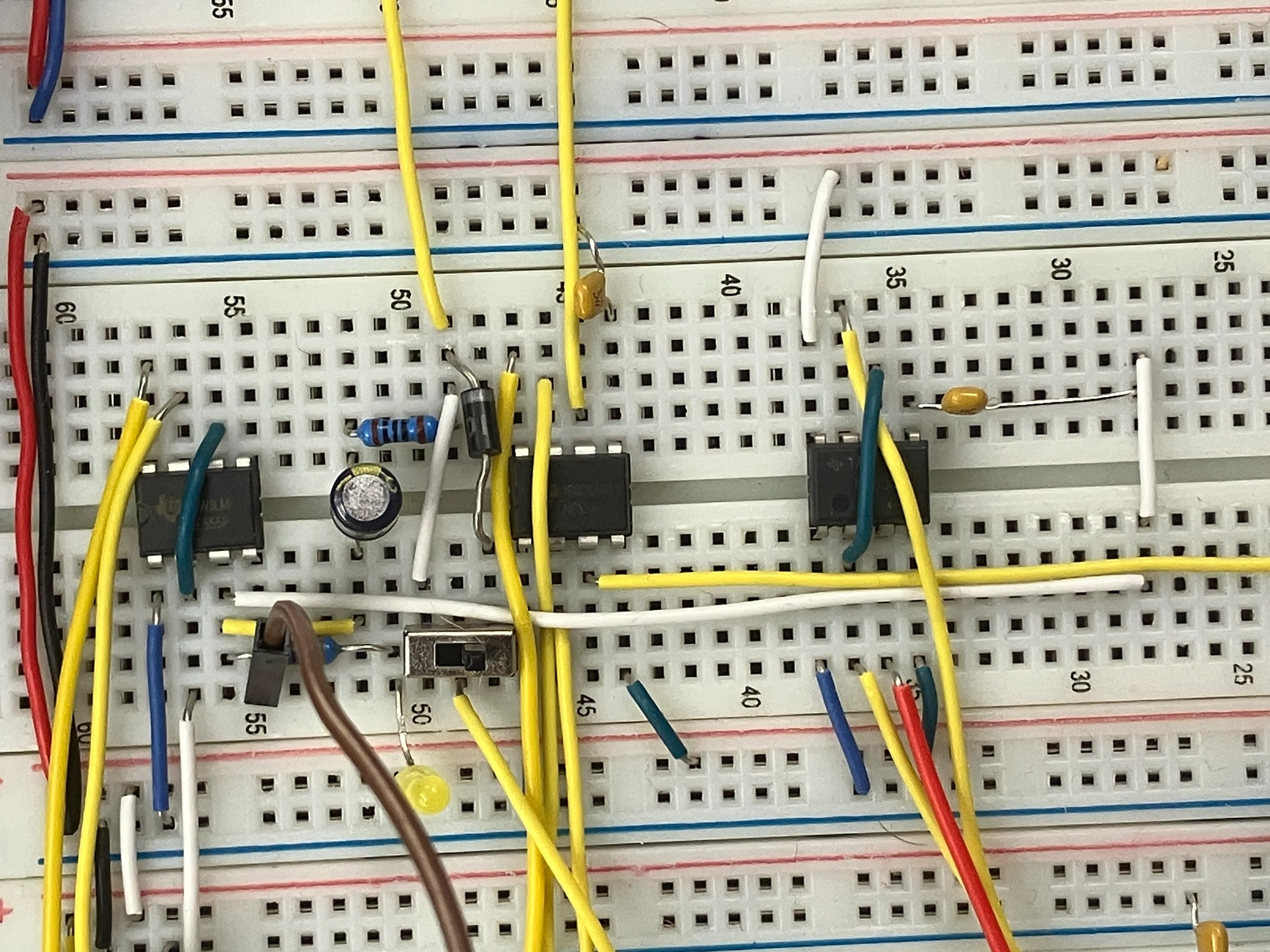
this circuit also worked like a metronome, but the ic got really hot. i still don’t know why. i built this circuit myself.
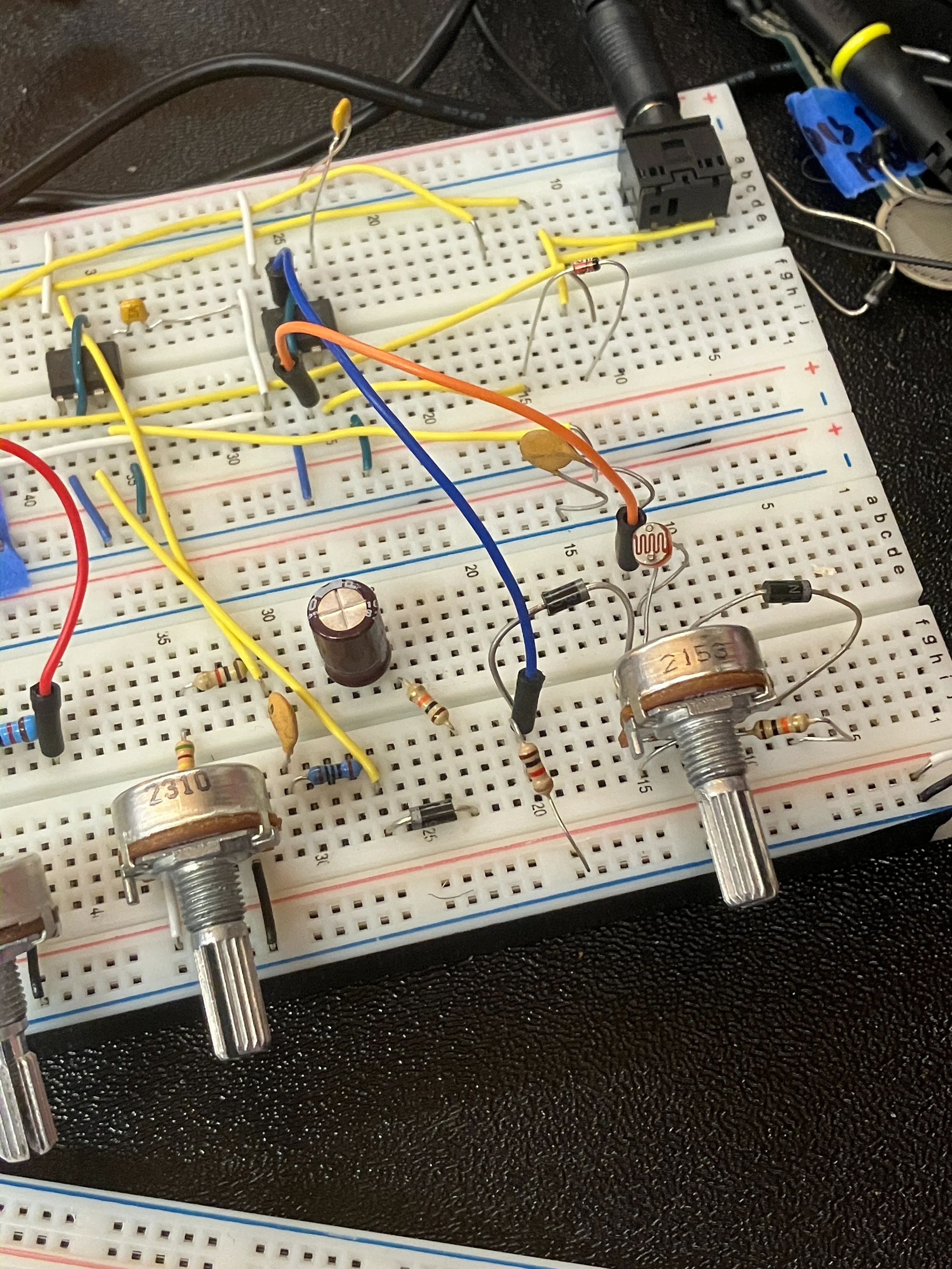
the next approach that i’m going to take is to build a bunch of circuits, and have them all separated on a big breadboard. that way, i can plug circuits in & out, and see what kinds of sounds i can produce (and layer). i know that the output of some 555 has to be the control of another, and that way it can on / off to produce alternating sound.
eventually, i can pick-choose the circuits i’m going to keep. let’s see.
251115:
my oscilloscope readings were all over the place. i don’t know why the signal isn’t clean, and why it pauses every time it takes a few readings. i then decided to change the duty-cycle, to be able to actually see what was happening (ivan suggested that this might be the case).
watched this: https://www.youtube.com/watch?v=Q5tcf1pYZRc
hell yeah!
i realised quickly that the pretty bit about this is the tangibility & the fact that you can mess around with it. i’m going to have two types of wires on my thing — one will be flat / solid (people don’t seem to want to take that out), and jumper wires (with a sign that says “mess around with any jumper wire”).
in the above circuit, i have no idea what i did. theoretically, i think by plugging in the output of the first circuit into the control voltage does something to the signal (distort it by multiplying), and then the resistance + capacitance value changes the timing. since it is related to (but not the same as) the first circuit, they have a little bit of a delay in between them.
actually, i don’t know. this is fun.
this is weirddddd! what is this:
for context: there is no photoresistor here, but current flows as my hand is on top.
i achieved an electric sounding effect with the inclusion of a third layer.
i spent a night messing around with my circuit.
first, i understood that with more layers, mixing became a problem. it didn’t play individual channels of sound, but rather added them together to create a single channel. that isn’t great, musically.
next, i understood that every component in this circuit affected the sound that is produced, because voltage gets split between the components.
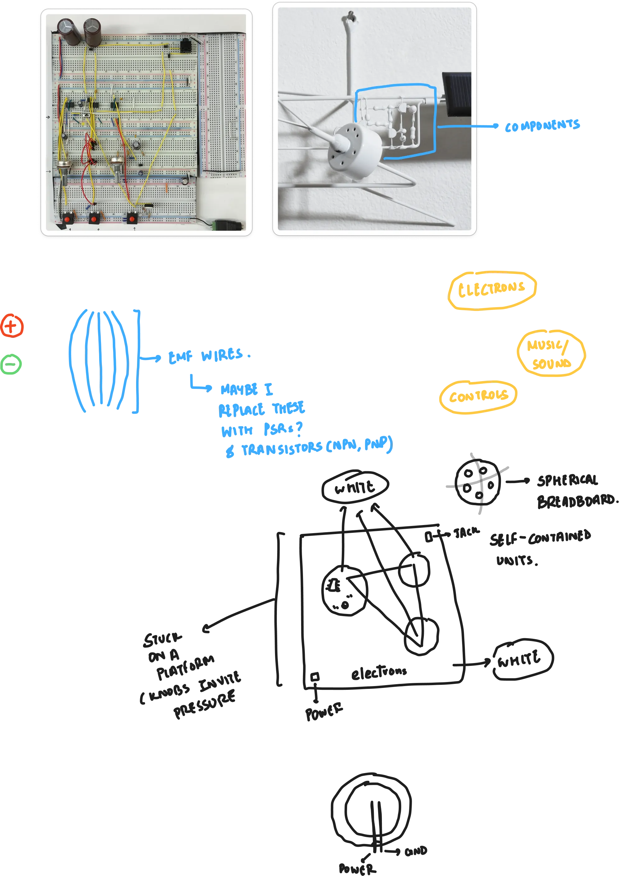
i then spent time trying to create a emf to manipulate with my hand.
it didn’t work.
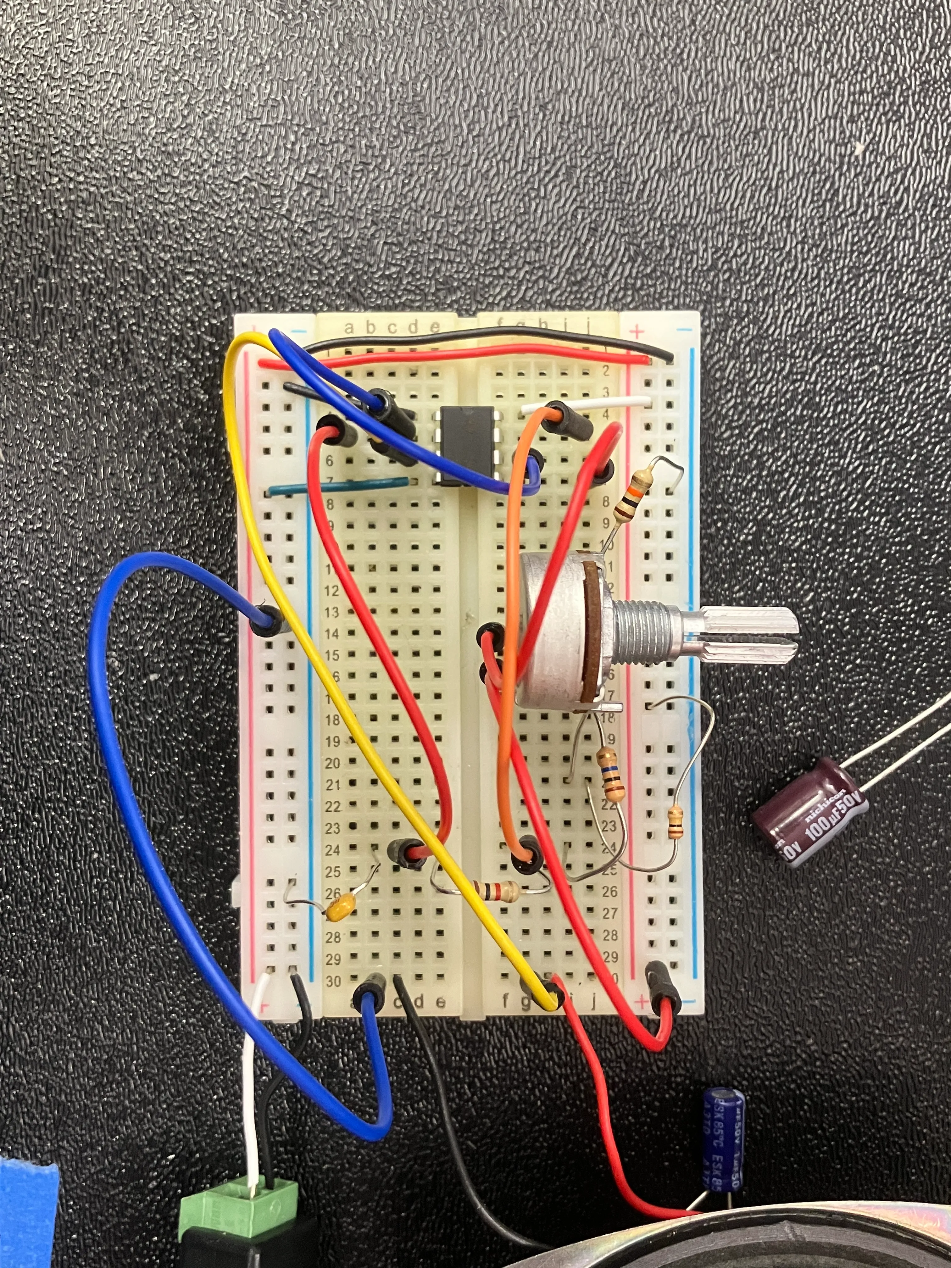
stripped the entire circuit, understood what every single thing was doing. took tom & david rios’s advice, and put decoupling capacitors on the power rail for cleaner sound.
achieved voluntary emf manipulation:
i just had to make bad circuitry on purpose.
spent too much time playing, had to remind myself to go home.
i know that i could keep playing around with this for a long, long time. i can add more things — such as a delay circuit, an op-amp, and more 555-ics.
but, i will remind myself what tom told me: what’s the bare minimum you need to do in this class, to be able to explore this further in the other classes?
i will play a teeny bit more, and then move to other parts of this: i.e, the physical interaction.
spent time cleaning up the circuit. had ordered toggle-switches, but they didn’t come. found 4 on the floor; made do with what i had.
i need to figure out mixing somehow. i have an idea to make my own mixer, with a bunch of potentiometers; but let’s see if i get it done before the playtest.
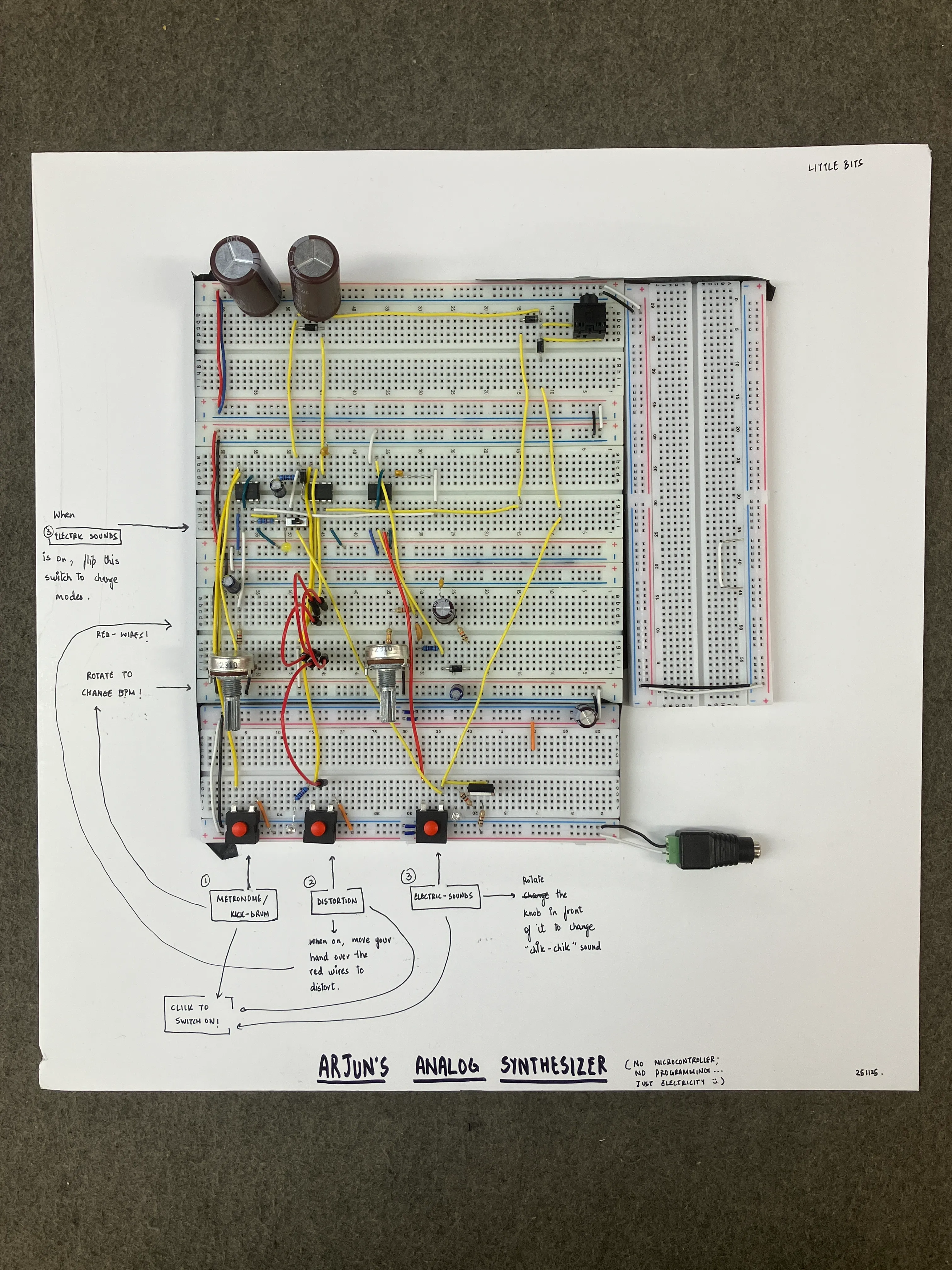
playtest (251126):
presented this:
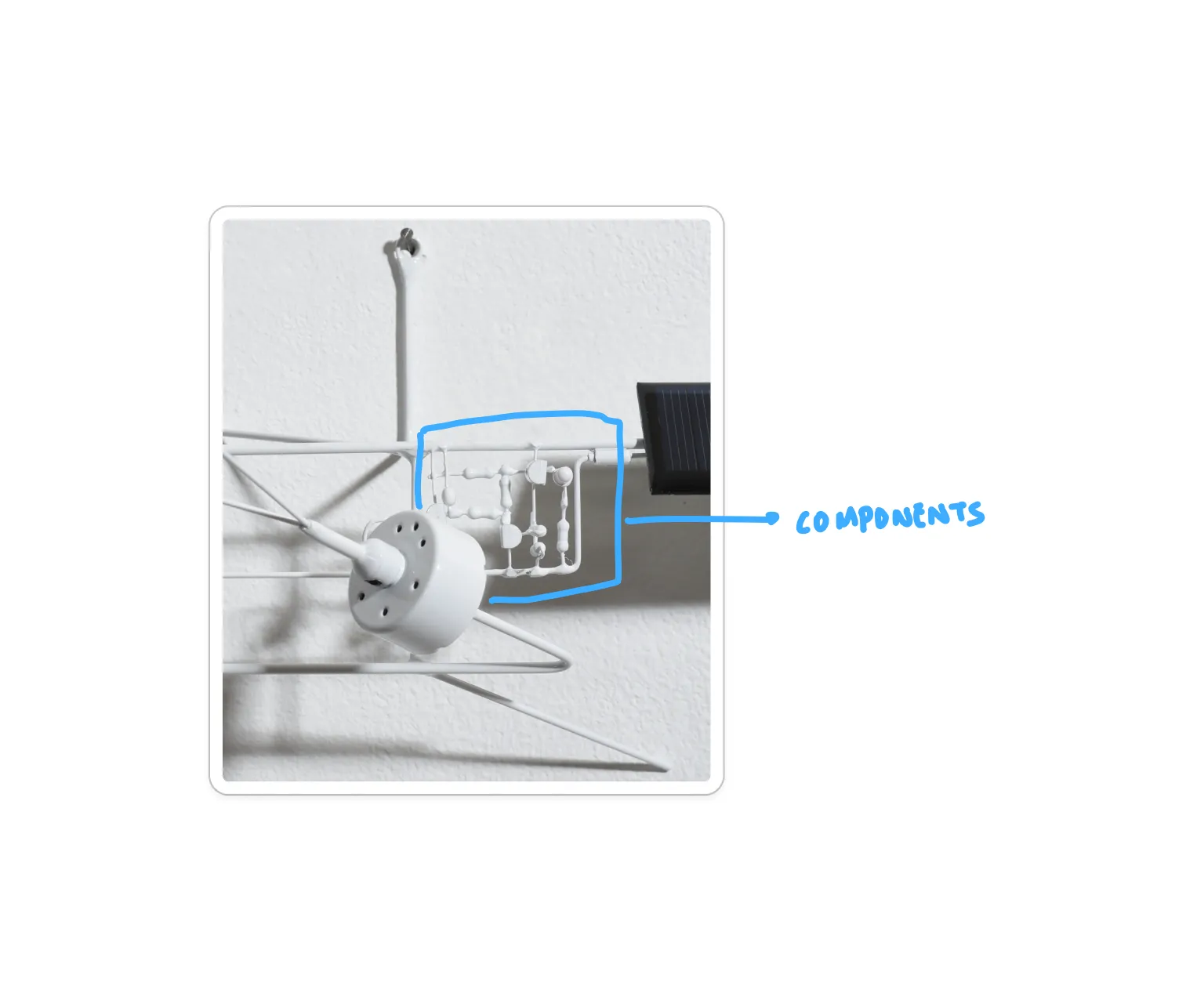
daniel rozin told me to think about the form that i present my project in. he suggested the work of bjorn schulke, and suggested me to make a ‘sculpture’ out of the electronic components; like so:
he also suggested that there is a sequential element in my project. the signal first gets processed via the metronome, and then can be distorted. he said why not make an invisible breadboard — show the components but hide the wiring.
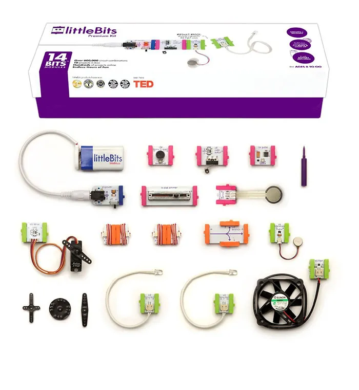
tom also recommended ‘little-bits’, and suggested modular units that could be plugged & played together. that is also an interesting approach — but i don’t think that i have the time to realise that vision now.
i observed that people press buttons linearly, and quickly, and expect immediate changes, to happen. my circuit takes a little bit of time — simply because of the way the capacitors are structured. the changes are also more subtle than people were keen to notice.
i also felt that people weren’t as patient as i wanted them to be — they kept hopping from project to project. that, however, will be the nature of a gallery-show too — why would anyone want to care about your project ?
that left me a bit puzzled. i loved making the thing that i made. there was so much beauty in those tiny circuits, and how the different components behaved. shloka, for example, understood it and spent way more time than anyone else in my playtest. it brings back the point: maybe my work is meant to be consumed by a tiny audience.
and i need to be okay with this reality. i, perhaps, will not make a mass-viral project in my life. it, in fact, is not even a part of my approach to itp.
so, i will make this choice, and i shall do so explicitly:
my project is not meant to be consumed by everyone. in fact, it is not designed to be consumed by everyone. i want to do justice to my curiosity — make the form follow my initial enquiry, and not be swayed by the idea of making it more ‘usable’ for the masses. if this causes academic conflict, i will argue that i know how to do so (with previous work), and justify that this project is designed keeping in mind a tiny audience.
next step: define the audience, and think about the subsequent form.
media from the playtest:
intentional change-making audience:
messing around audience:
shloka just playing with distortion:
spent time thinking through the final form.
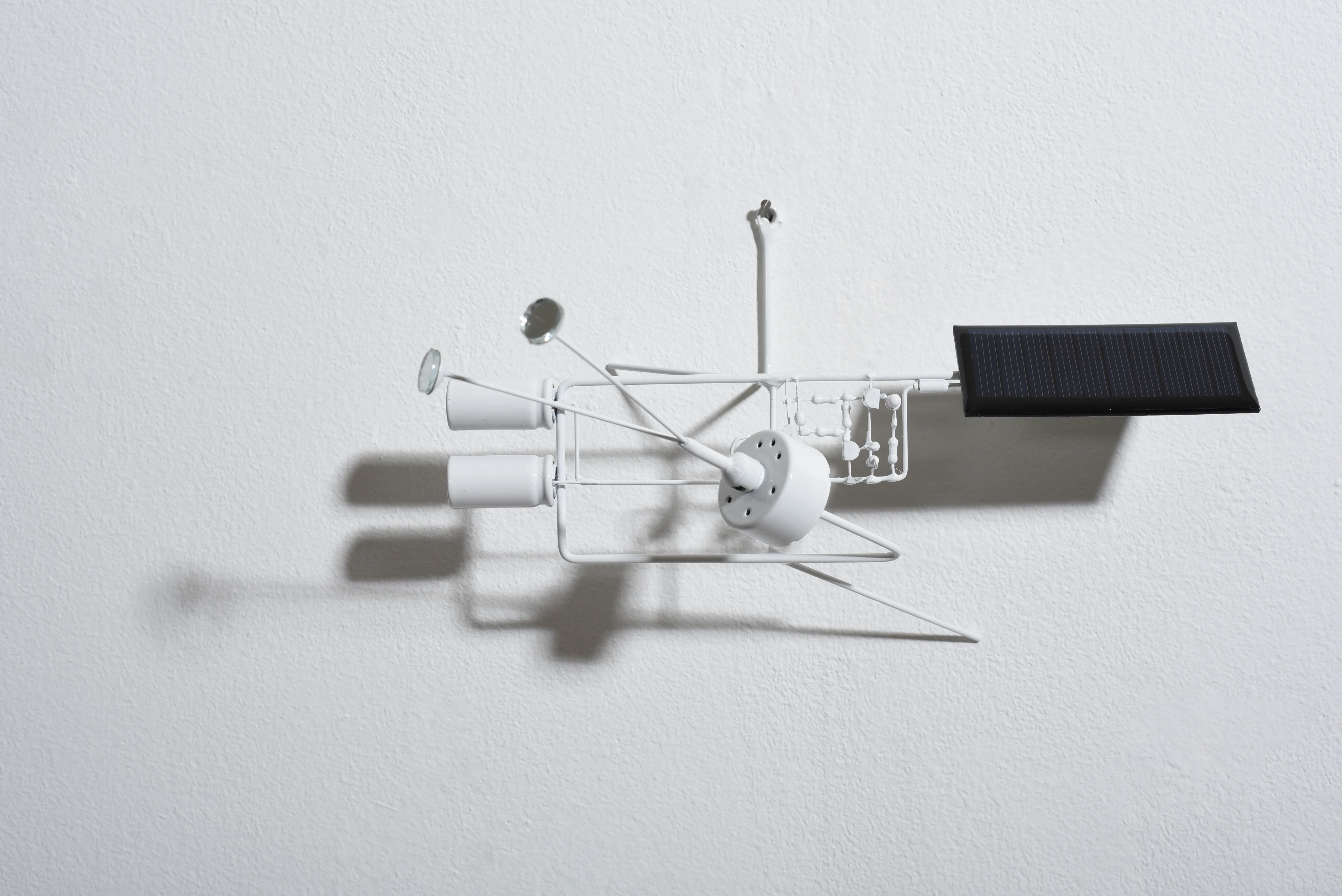
inspiration:
 in case it isn’t clear, the idea is:
to produce 3 small spheres, with components mounted on top of it. the spheres are connected to each other (since my circuits are connected to each other). the spheres are metaphors for electrons, which together produce sound. the platform on the bottom could be my power & ground rails.
everything is white, so as to take focus out of the structure, and focus attention on the manufactured-colour(s) of the components instead.
i spent time trying to understand fusion. i realised that i could spend time and learn how to model a sphere with holes cut (and then 3-d print it). however, it wasn’t worth the effort. i would need a specific number of holes for each circuit. it would be better to make a sphere that could be dismantled (half & half), and drill the holes myself. i would, however, still need some sort of power & ground rail inside each sphere.
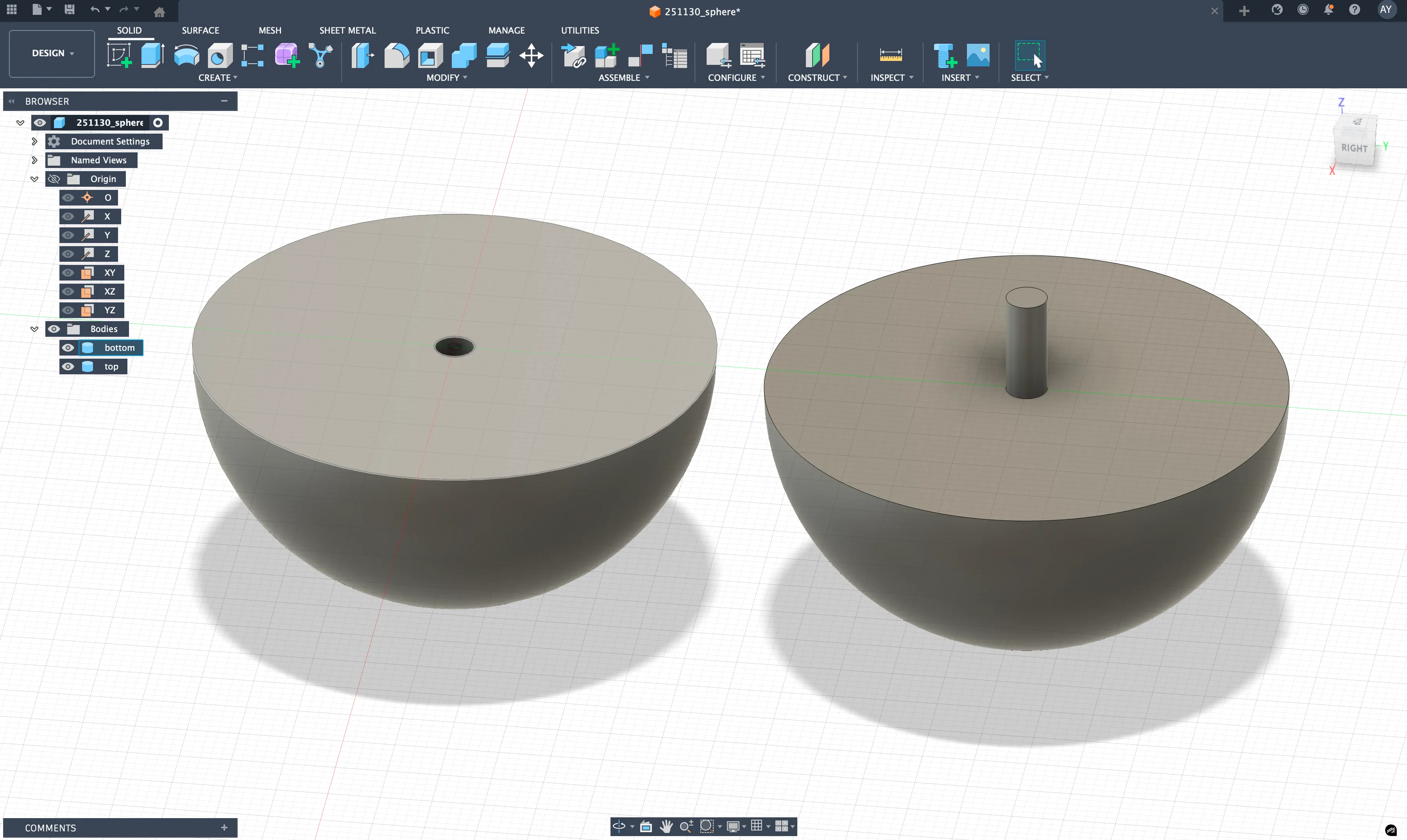
the 3-d printer auto-converted my dimensions into mm. stupid shit. now i have to wait until the printer is empty again, to be able to prototype this.
tried more 3-d prints:
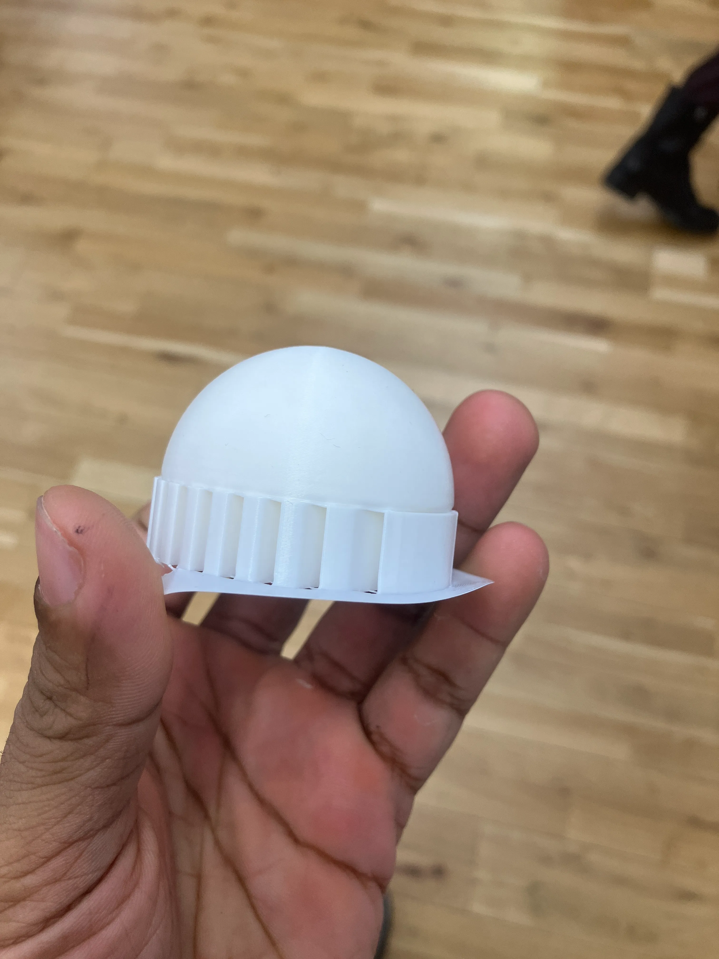
realised that making a spherical breadboard was too complicated. spoke to tom, aram. decided to make something flatter — but i really want to play with some sort of dimensionality too.
my brain is too consumed by the problems i’m facing in hypercinema (final-project-log).
251206:
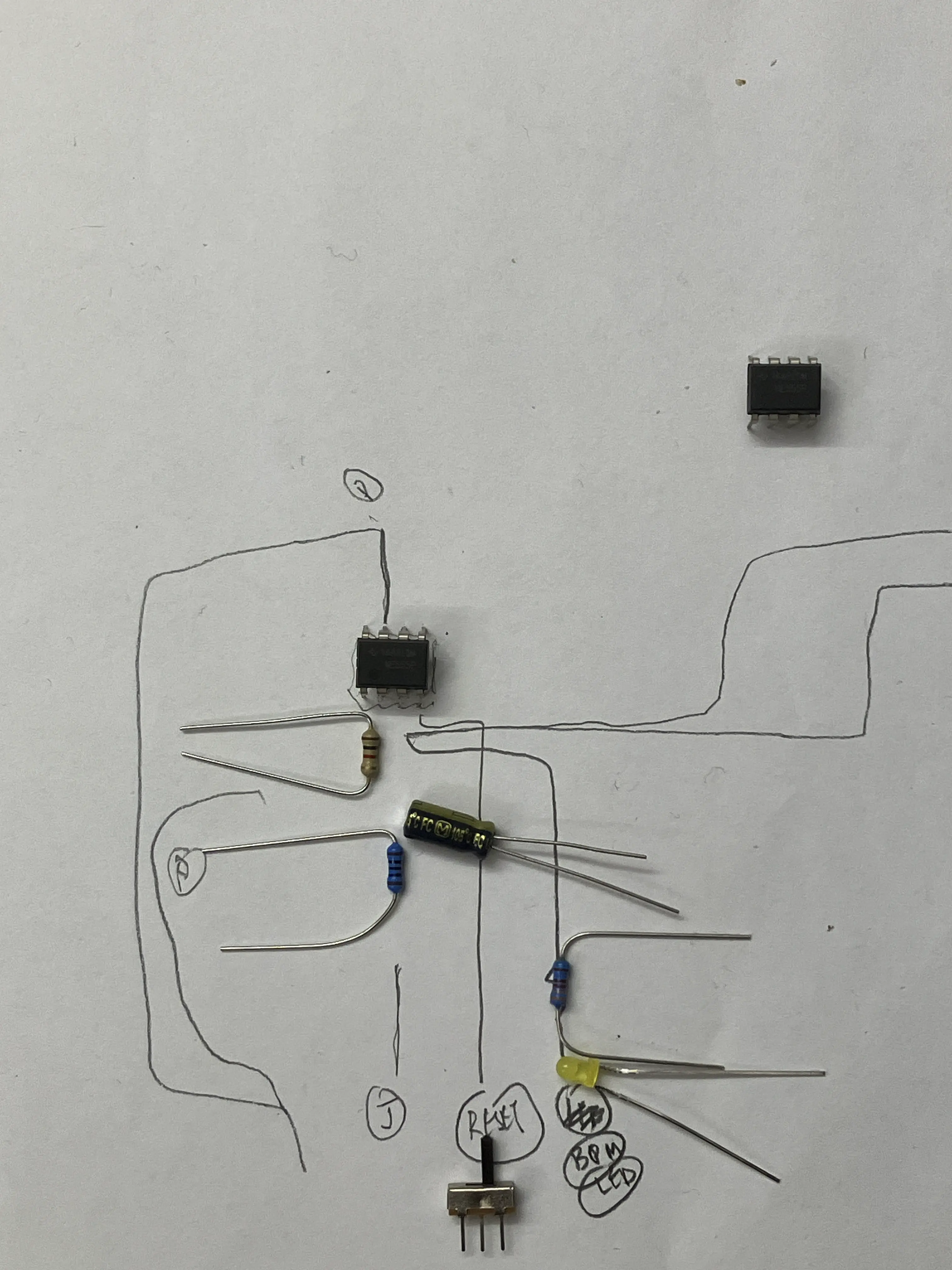
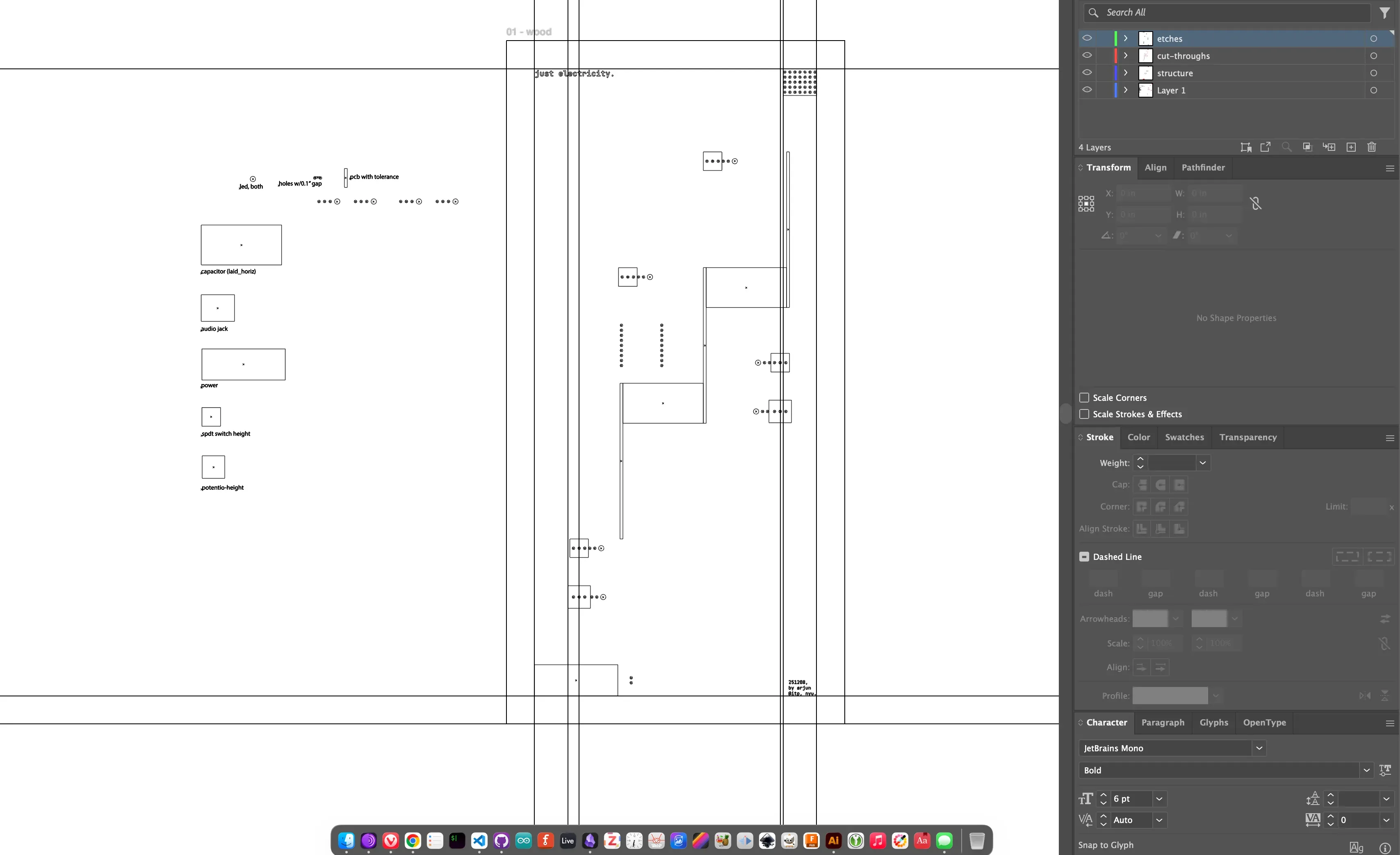
i began sketching out a schematic on fritzing.
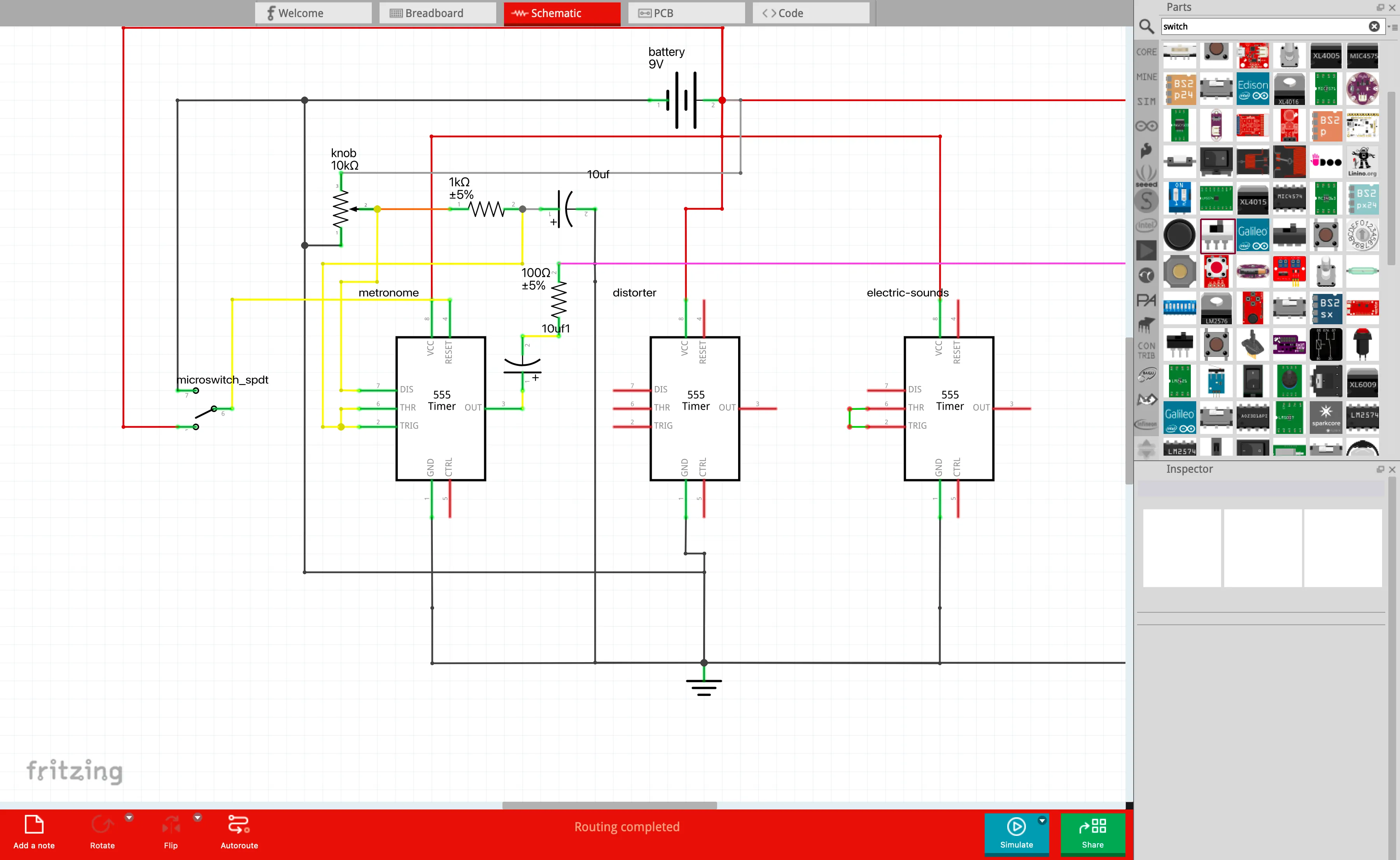
it took me about an hour to get the hang of fritzing, and make the schematic for the first one. i quickly realised that my circuit was a little complicated.
at this point, gabriel suggested that i just draw the circuit out by hand and get to soldering. he was right — it was more important to get to soldering than to draw a pretty circuit. so, i did that.
but, when i started drawing it, i realised that the structure of my software was helping me be more rigid, and it would also result in a better schematic. so, i continued with what i was doing.
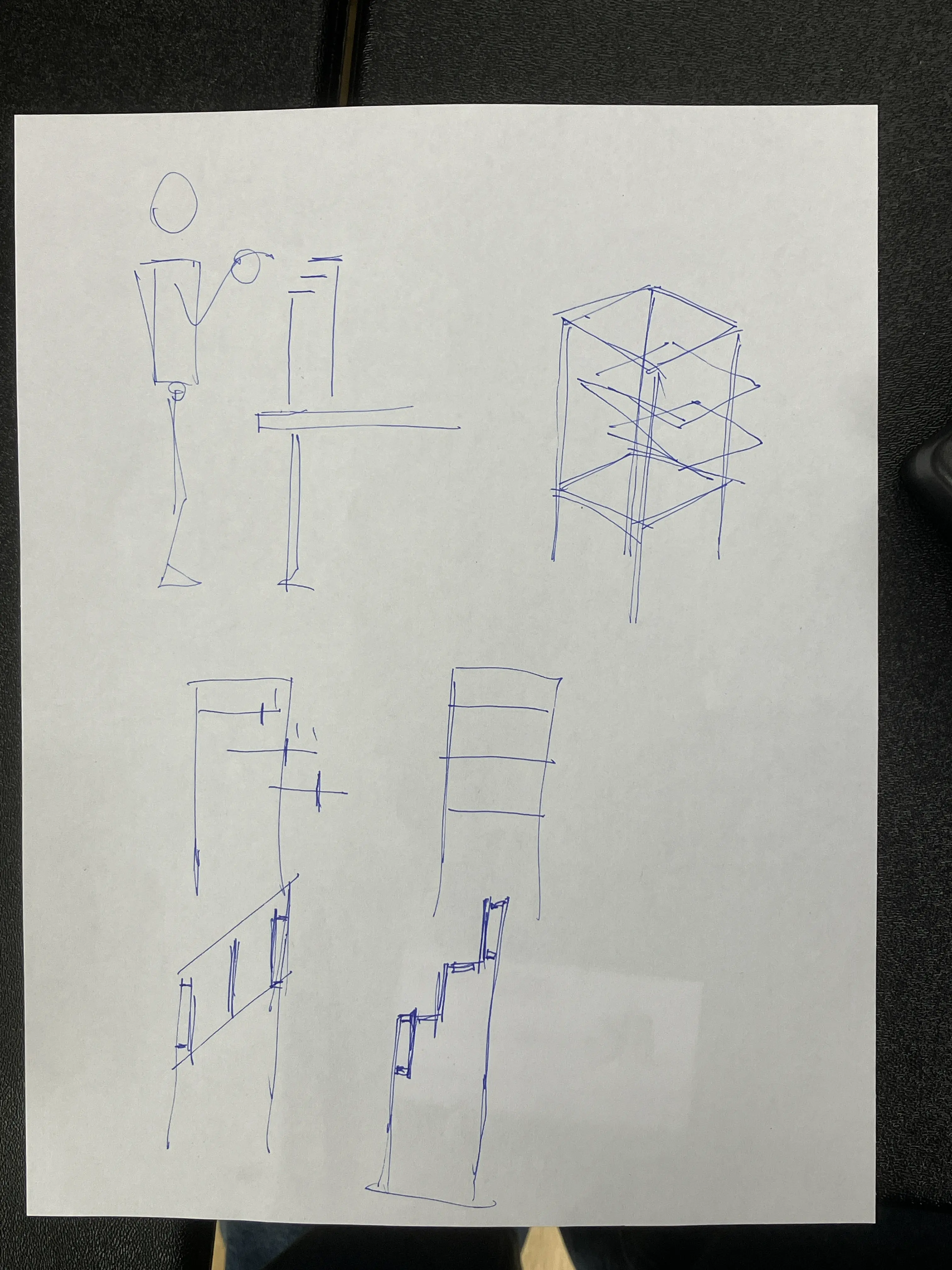
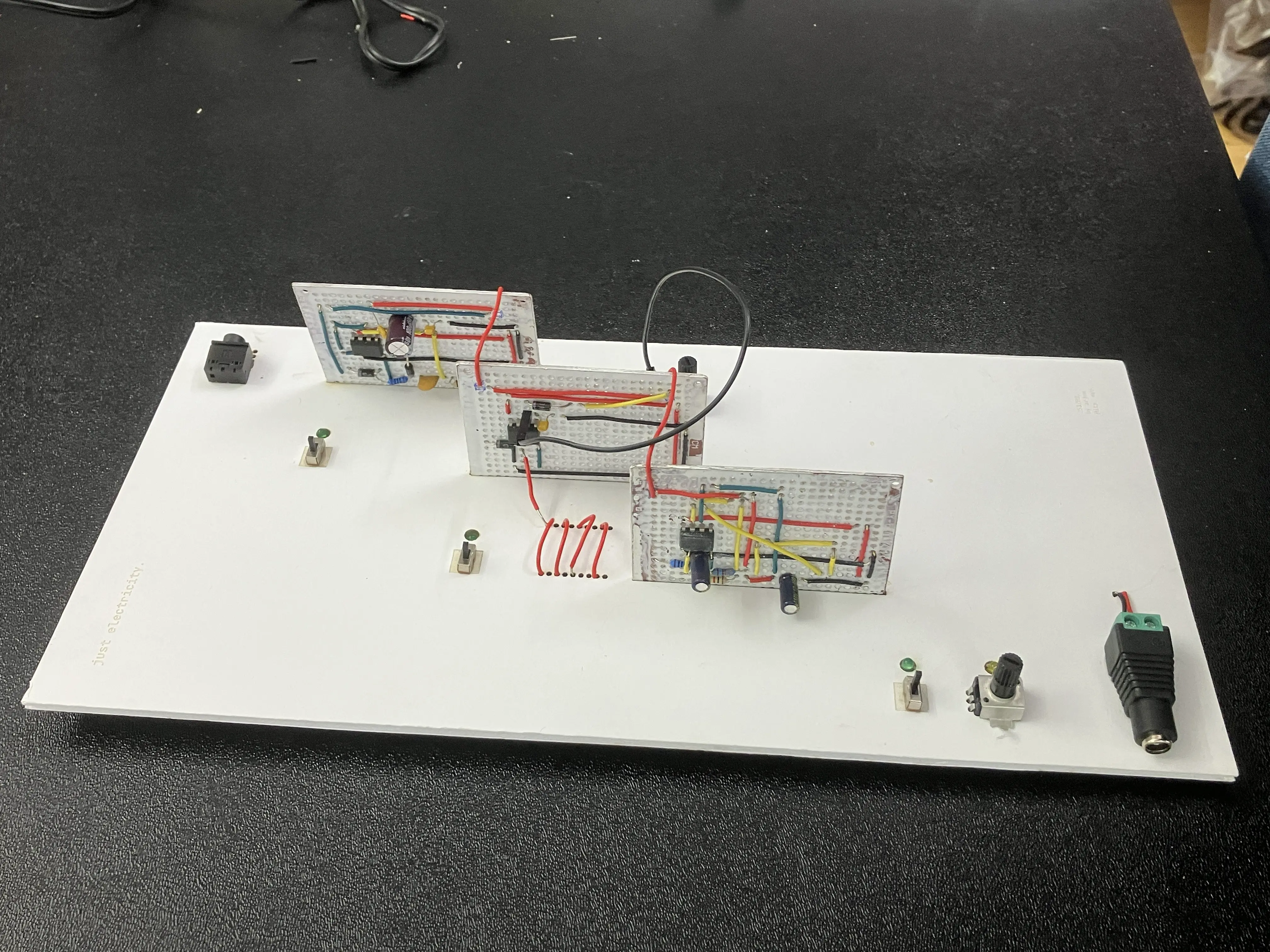
i spent time thinking through the form. tom’s voice “think about the interaction” kept looming in my head. aram also reinforced it when i was thinking of going in a more sculptural direction.
the idea was to mess around with planes; i.e: one one plane (when you look top-down), your job is to interact. when you look from the left, your job is to admire (or be curious about) the components. and, when you look from the right, your job is to admire the wiring.
i quickly understood that the fabrication of this would take me time. i have two days, and a bunch of other finals work to finish. i don’t know what i’ll do yet.
the problem is that there are many interconnections between the different circuits. it was easy to do so on a breadboard, because i wasn’t worrying about the aesthetics much: i wanted the sound to work, and to understand what was happening.
but now, especially after the midterm, i know that fabrication requires time — perhaps more time than i spent in circuitry. but that’s impossible, unless i figure out how to stretch a day beyond 24 hours.
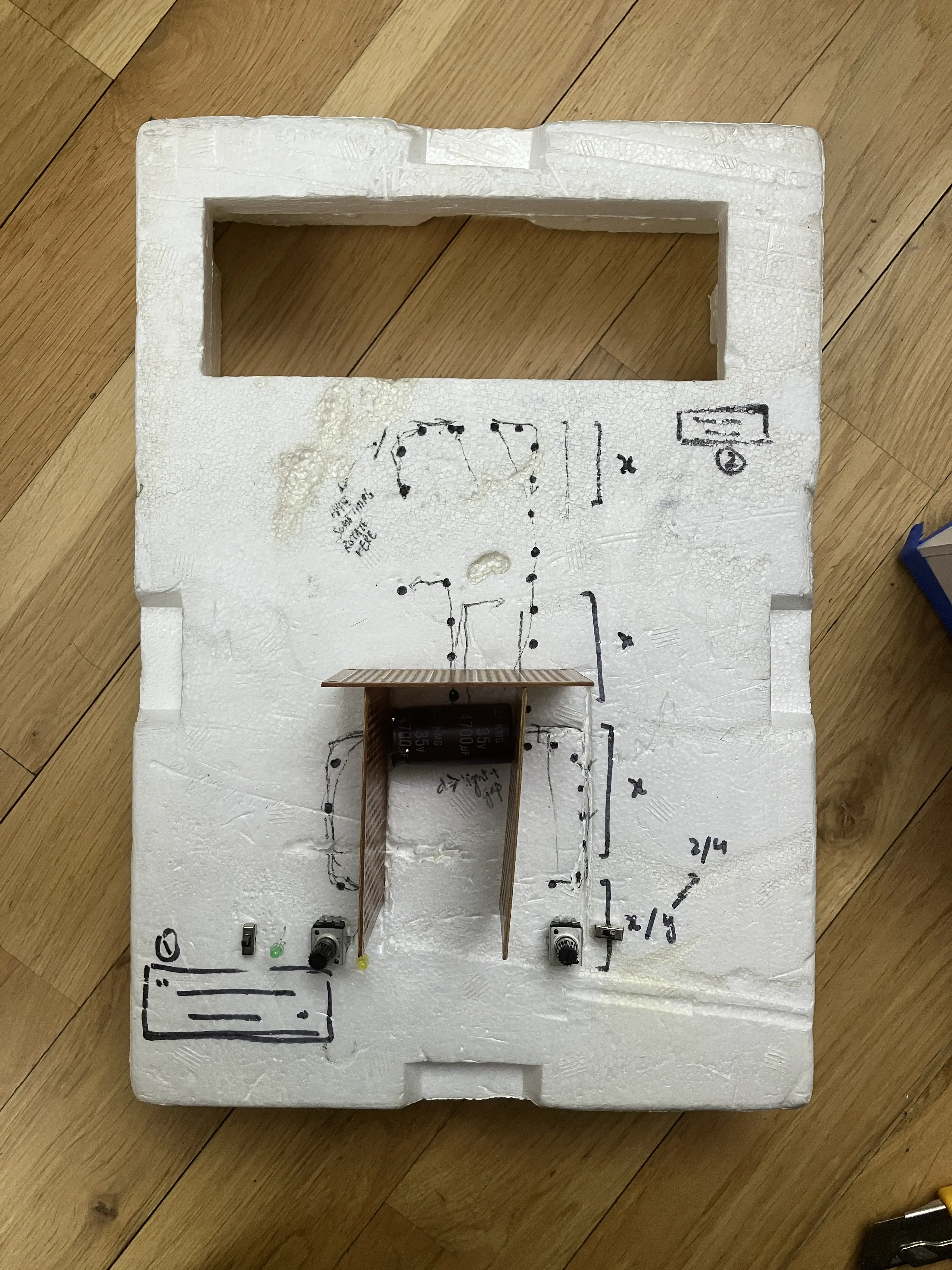
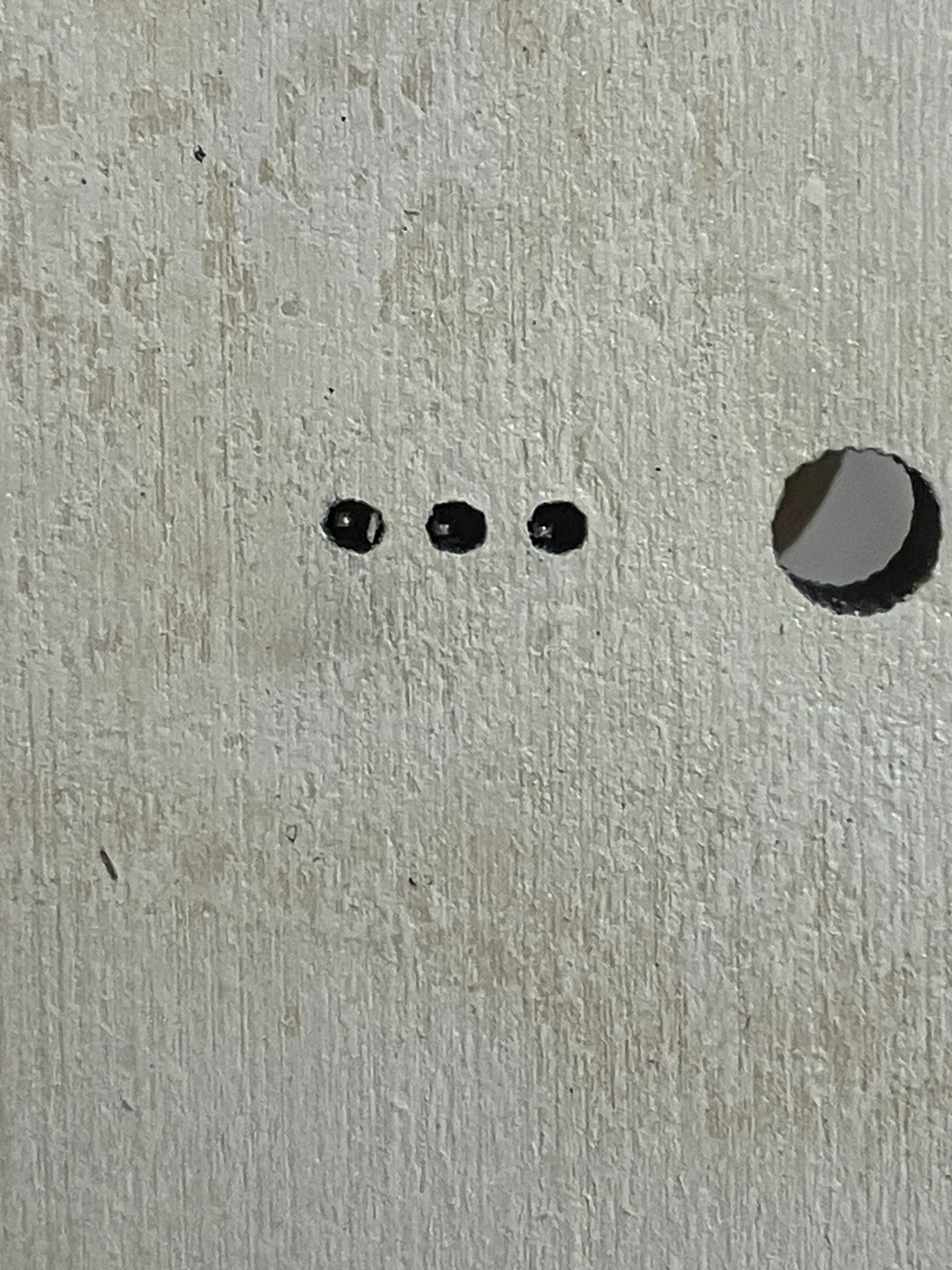
i sketched out the schematic to laser cut wood.
the pins didn’t reach the bottom of the panel. the wood was too thick.
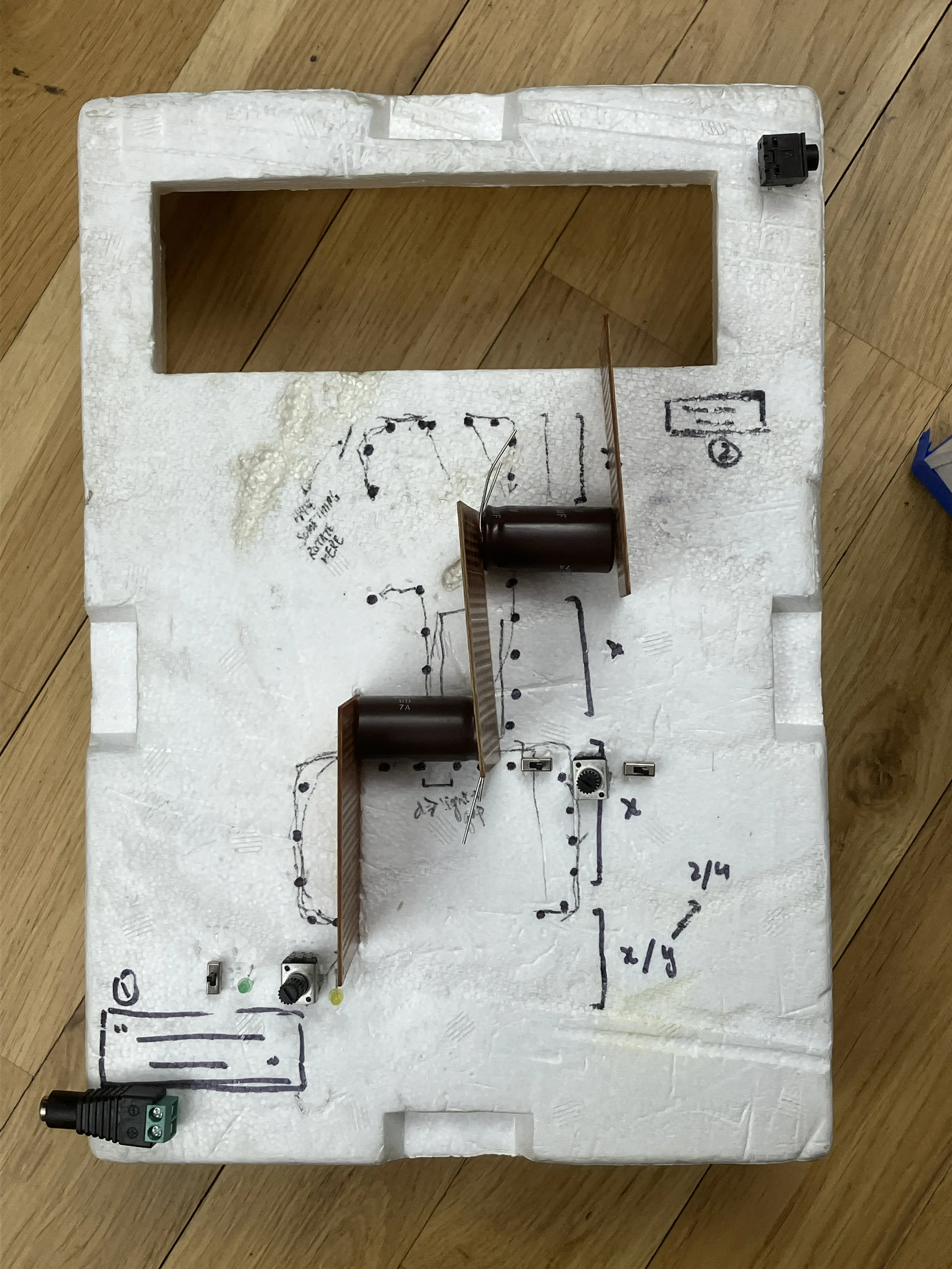
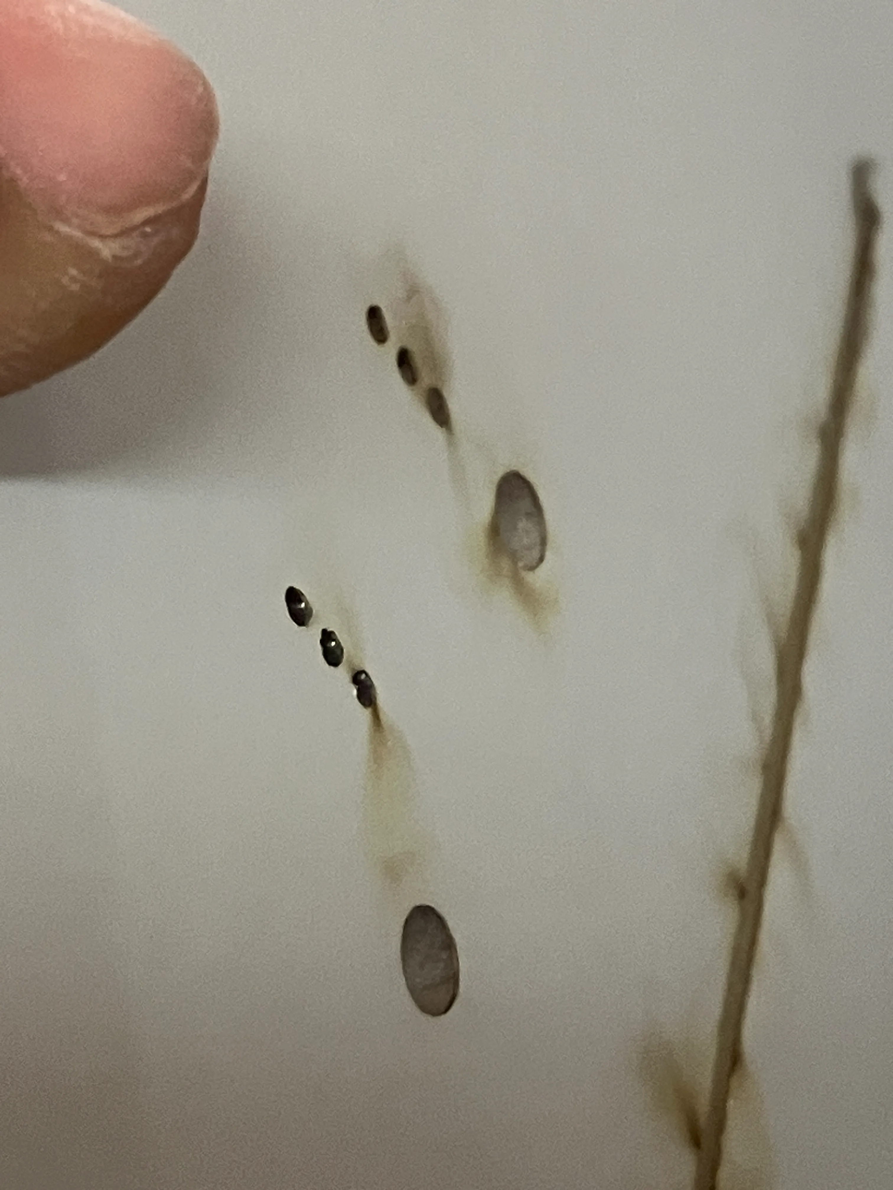
burnt the foam board:
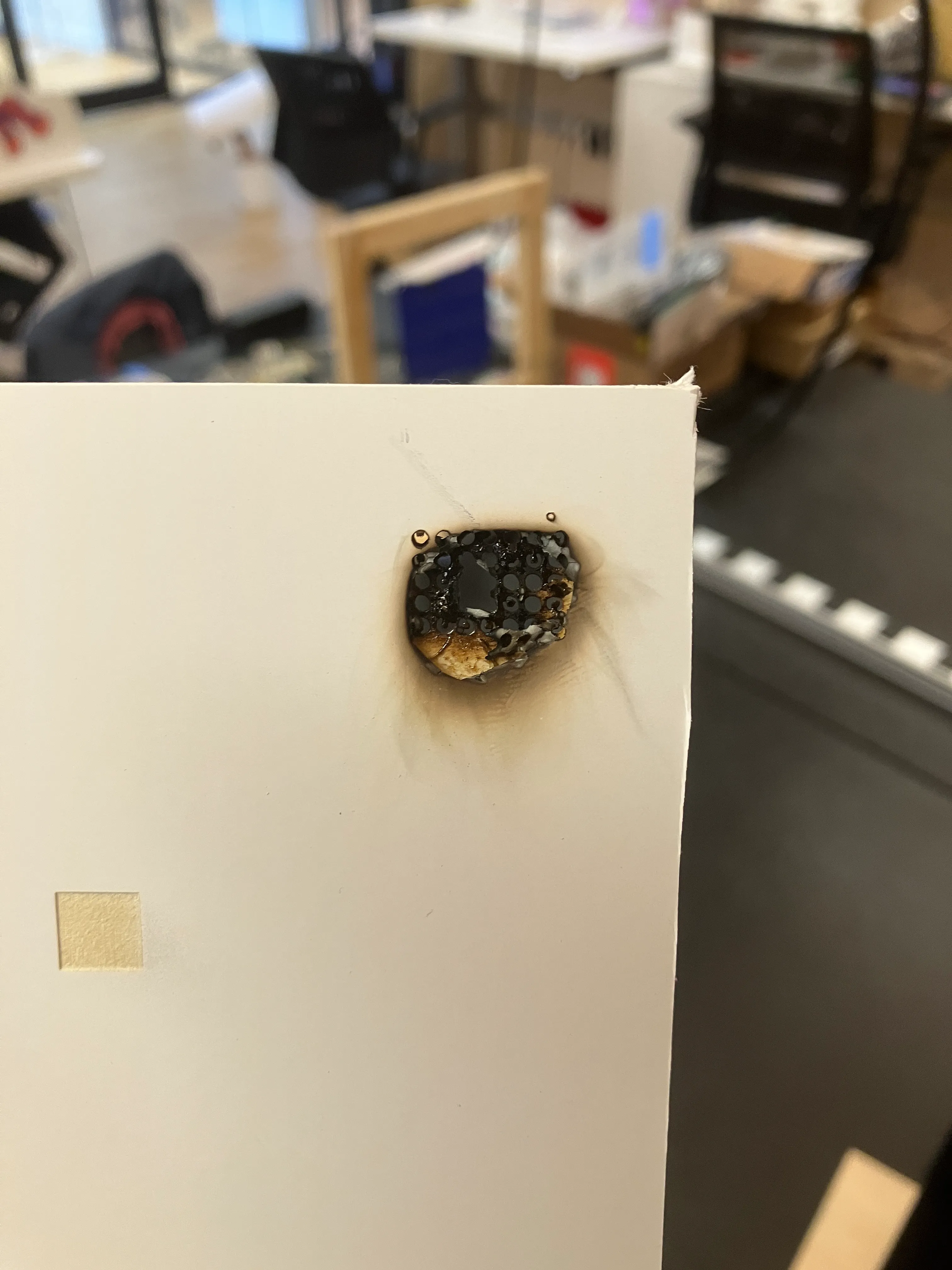
lowered power:
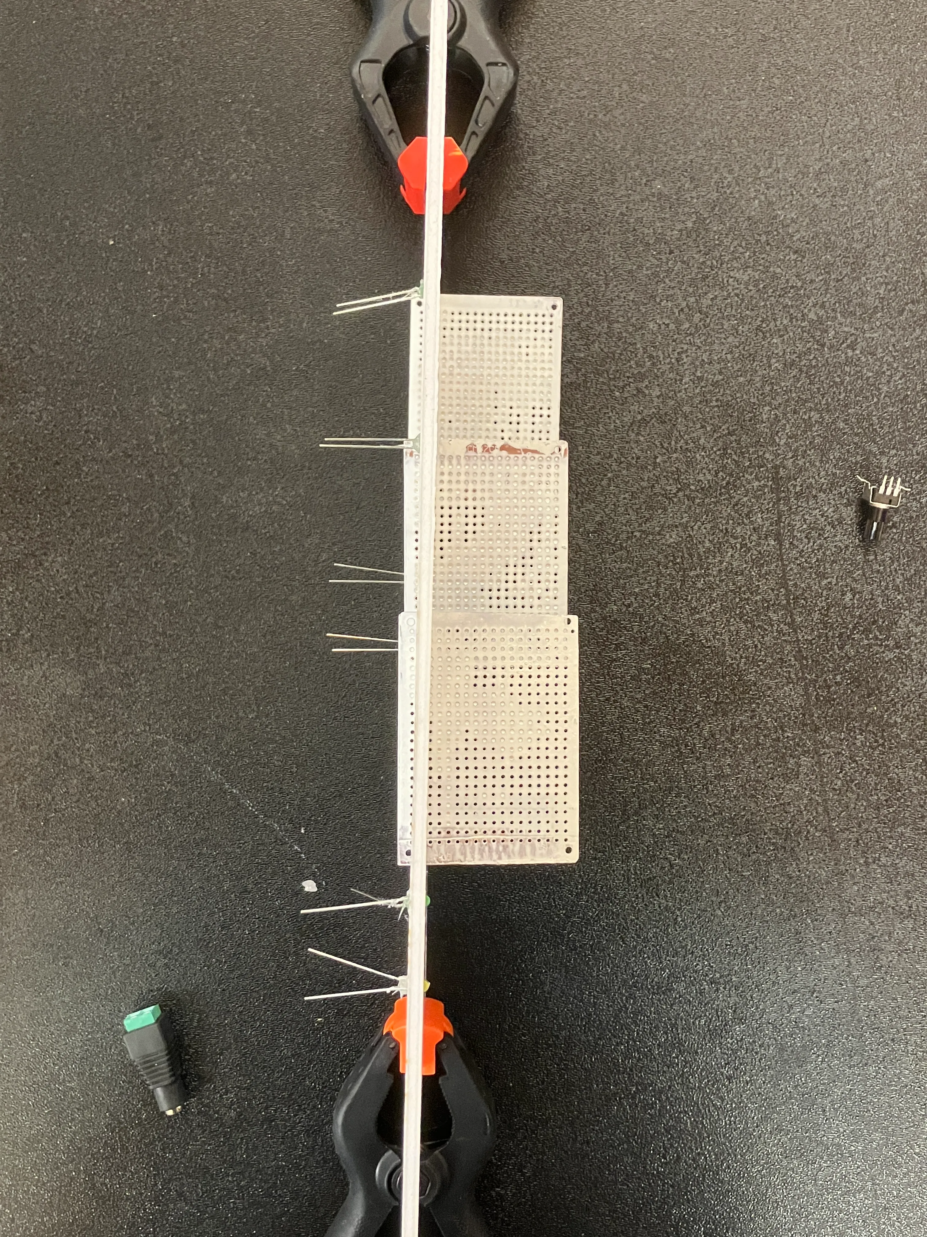
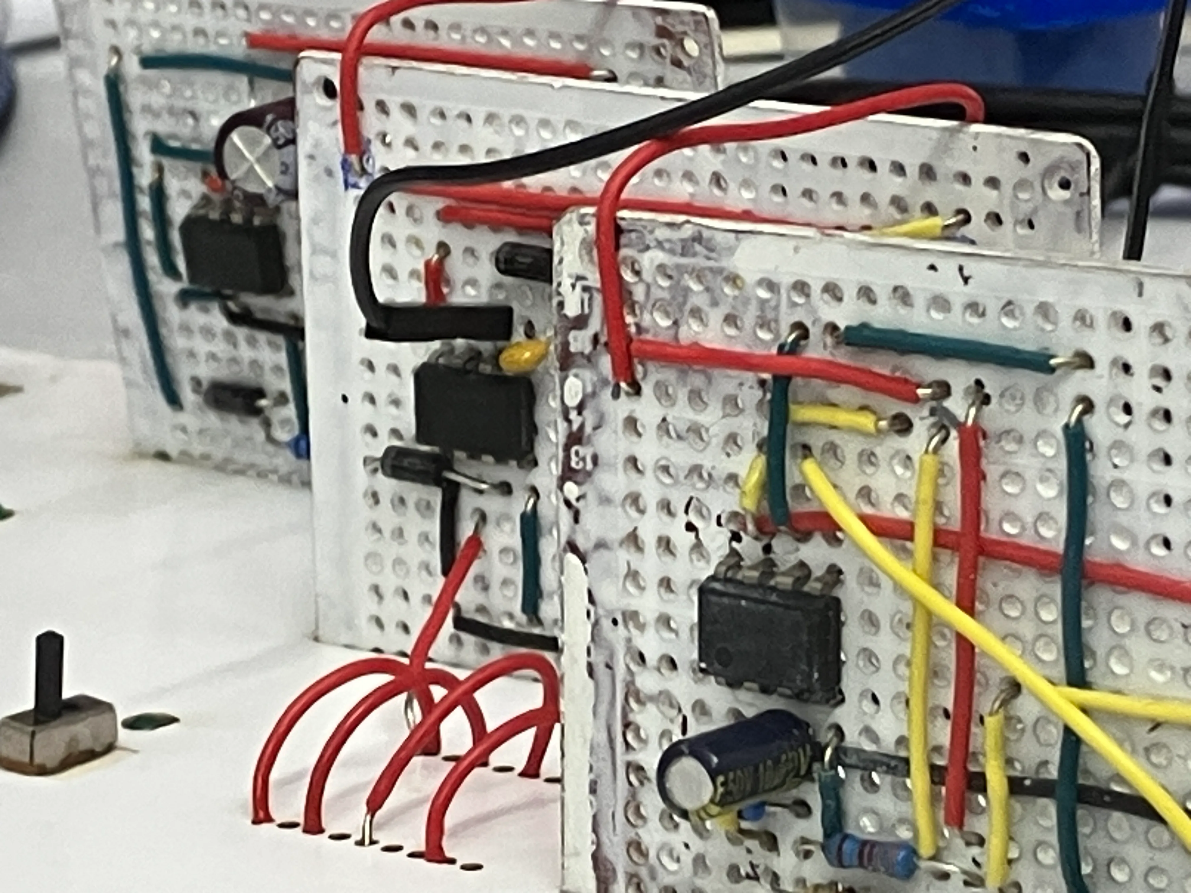
soldered one circuit painstakingly. realised i didn’t have enough space. it became a pain to do this.
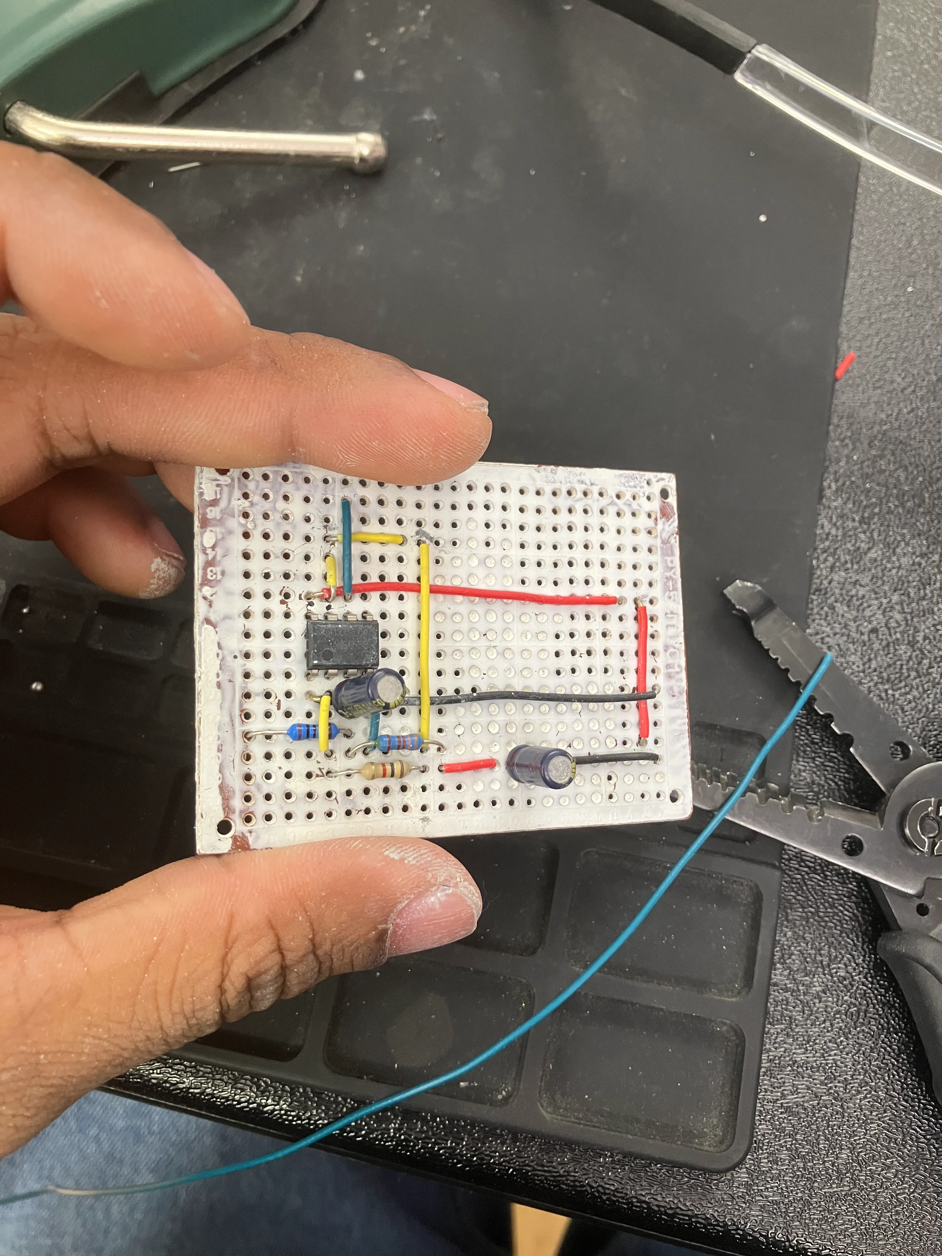
spent the whole night soldering. didn’t get very far.
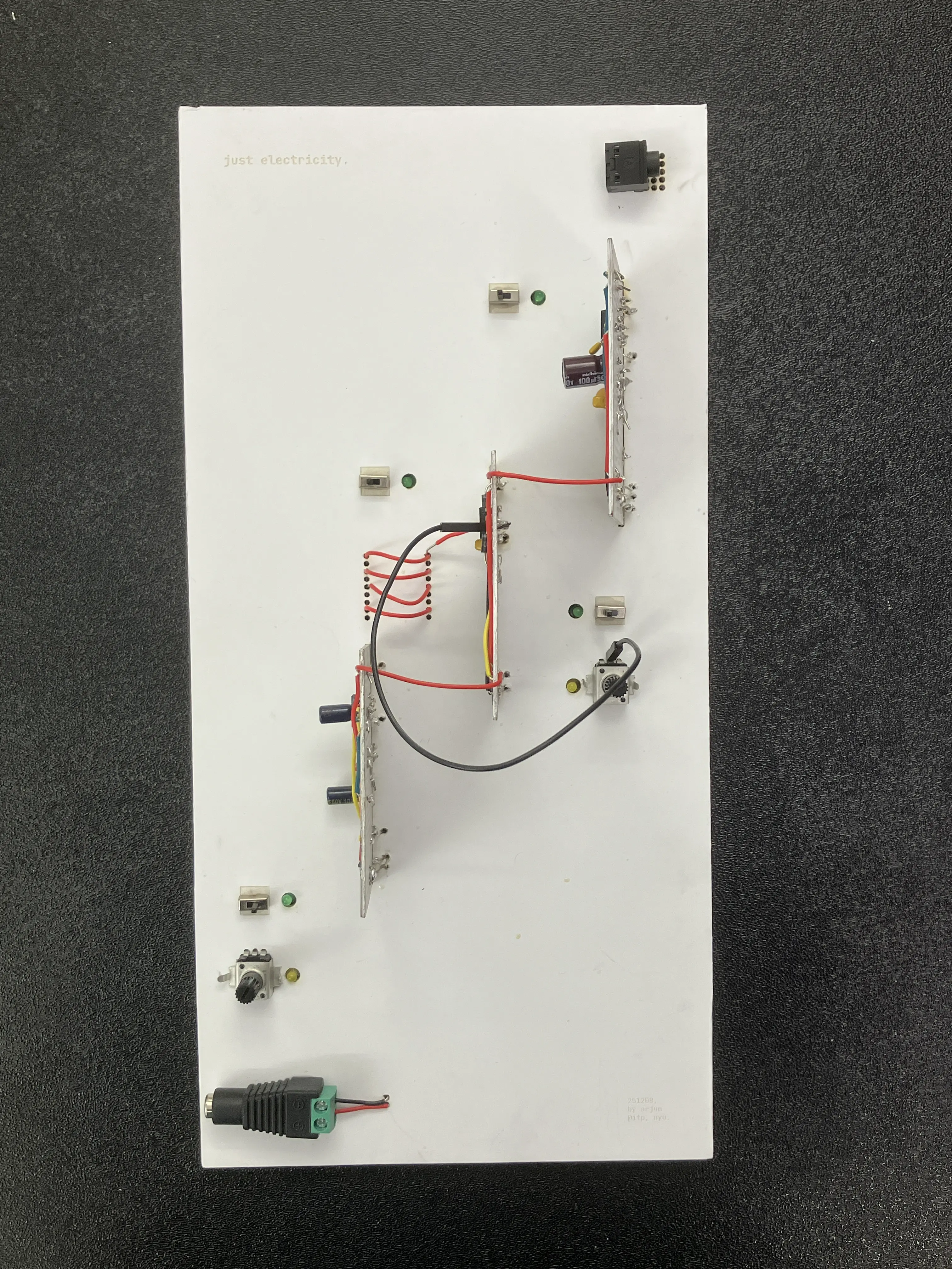
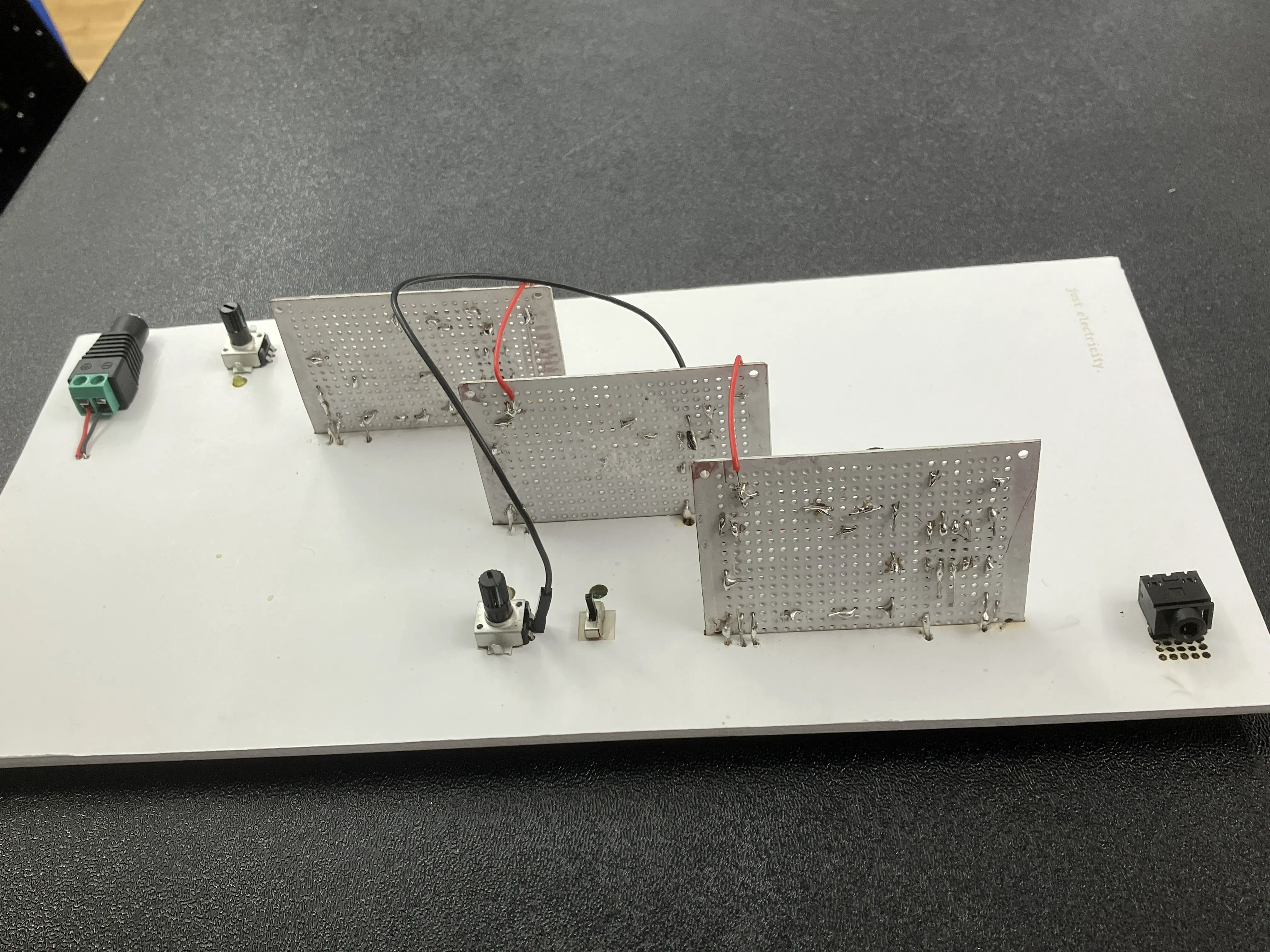
it’s beginning to look pretty though; prettier than the physical-thing i made last time.
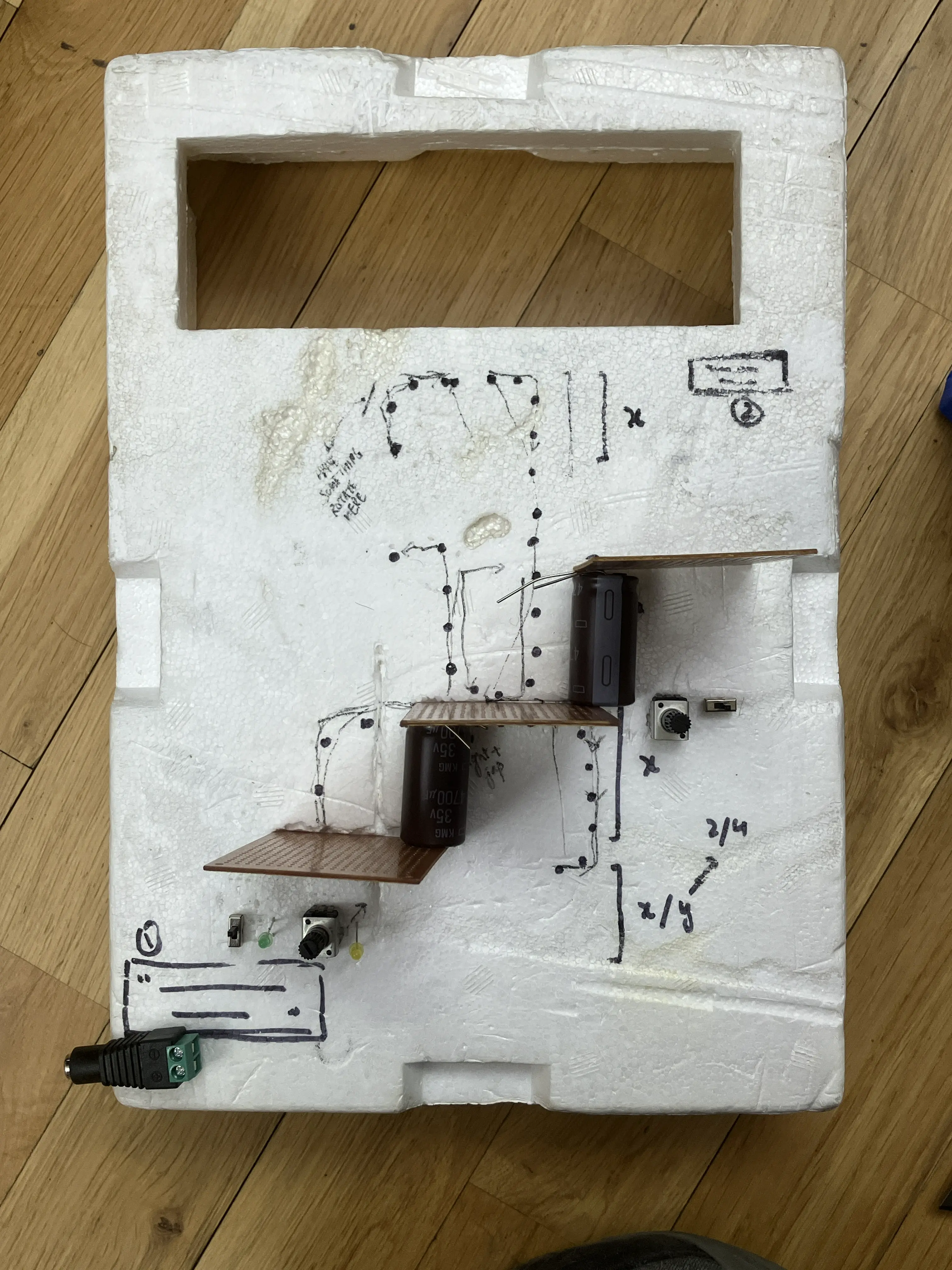
when i soldered things together, my circuit didn’t work the way it did on the breadboard. however, because i had made many circuits with the 555 before this, i was able to quickly build up a circuit and compare to debug.
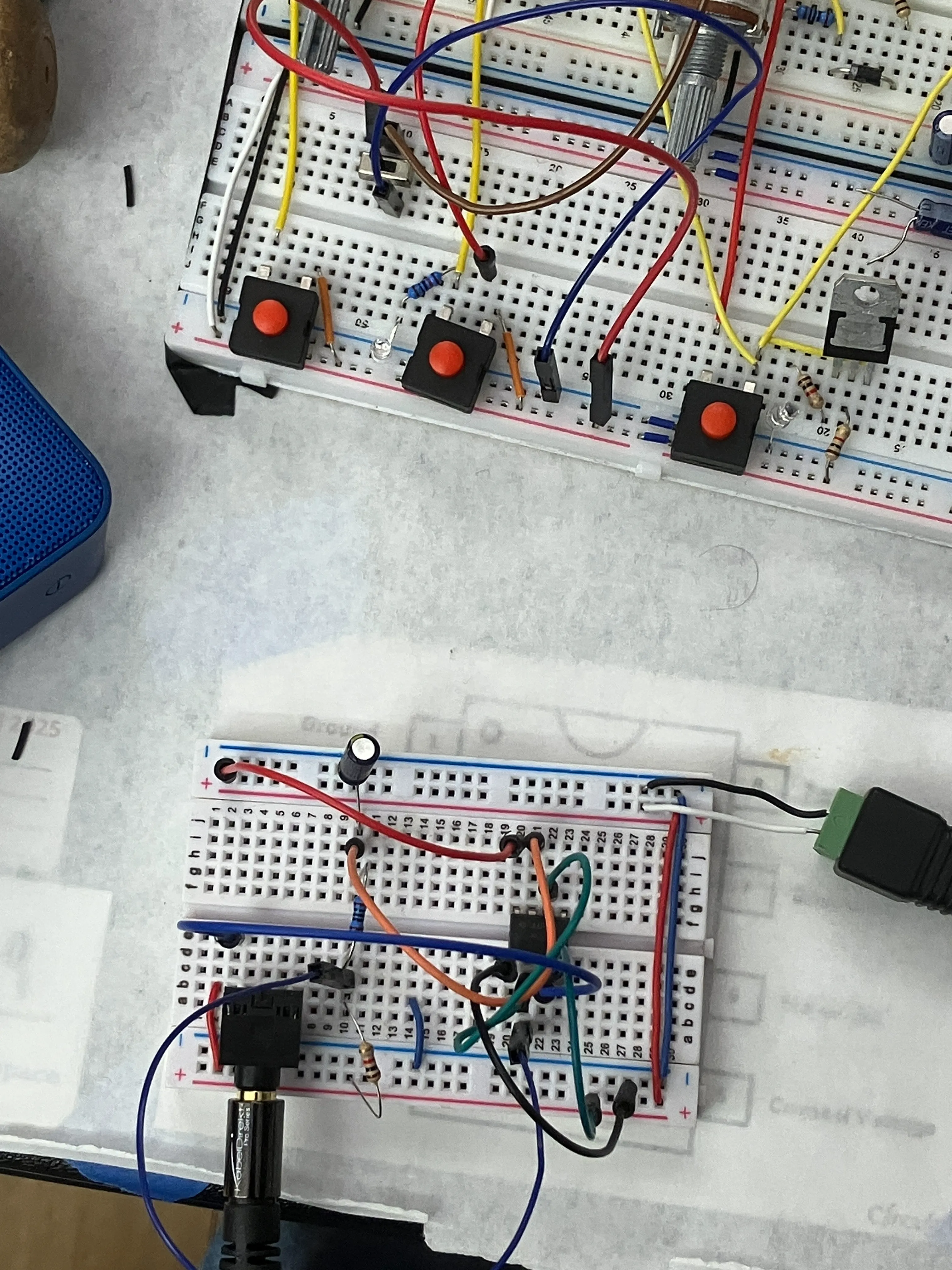
my guess is that it had something to do with components being in a certain order that i messed up, thereby removing the resistor-bridge between trigger & discharge.
got the circuits to work. spent another night soldering.
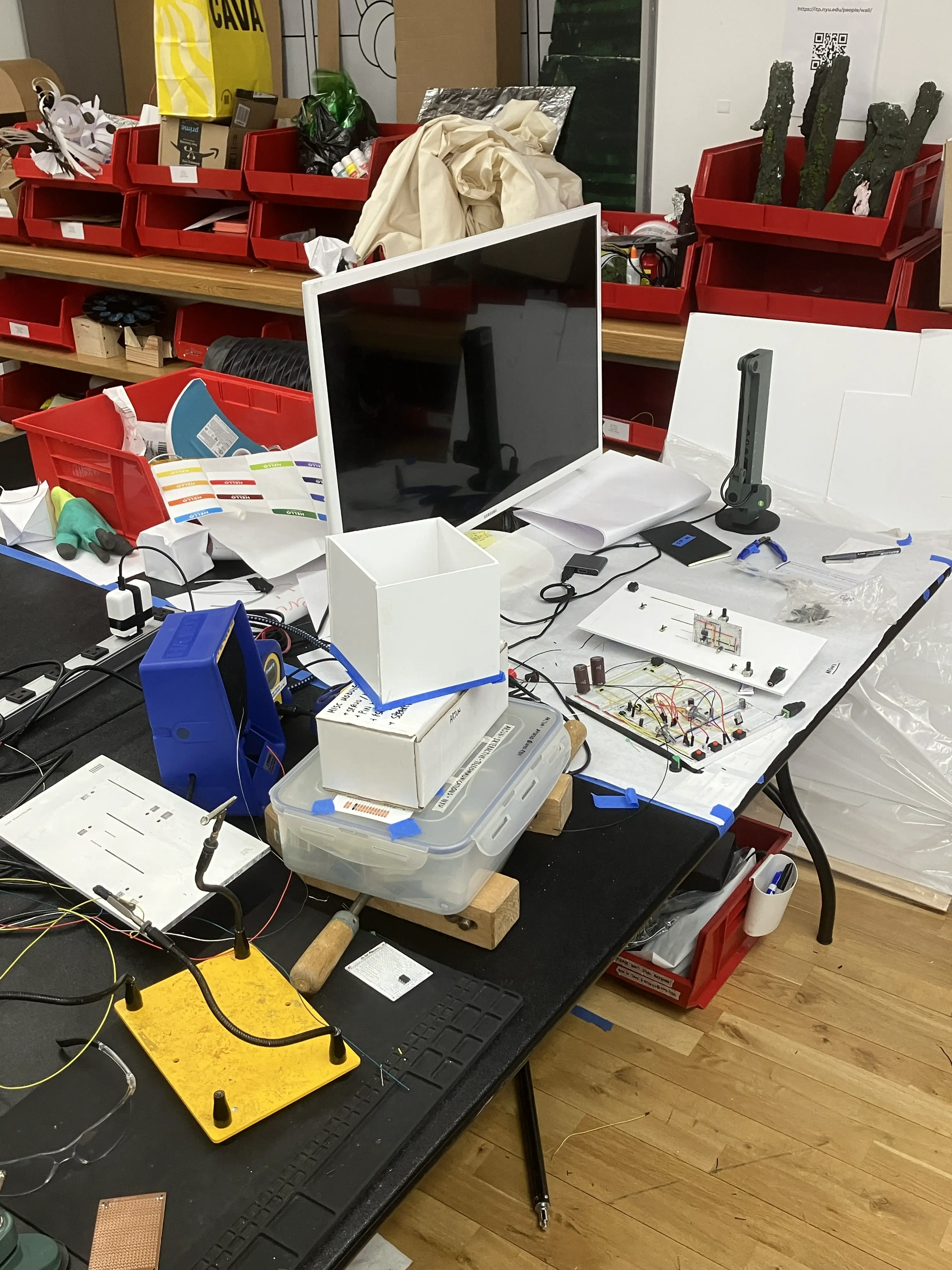
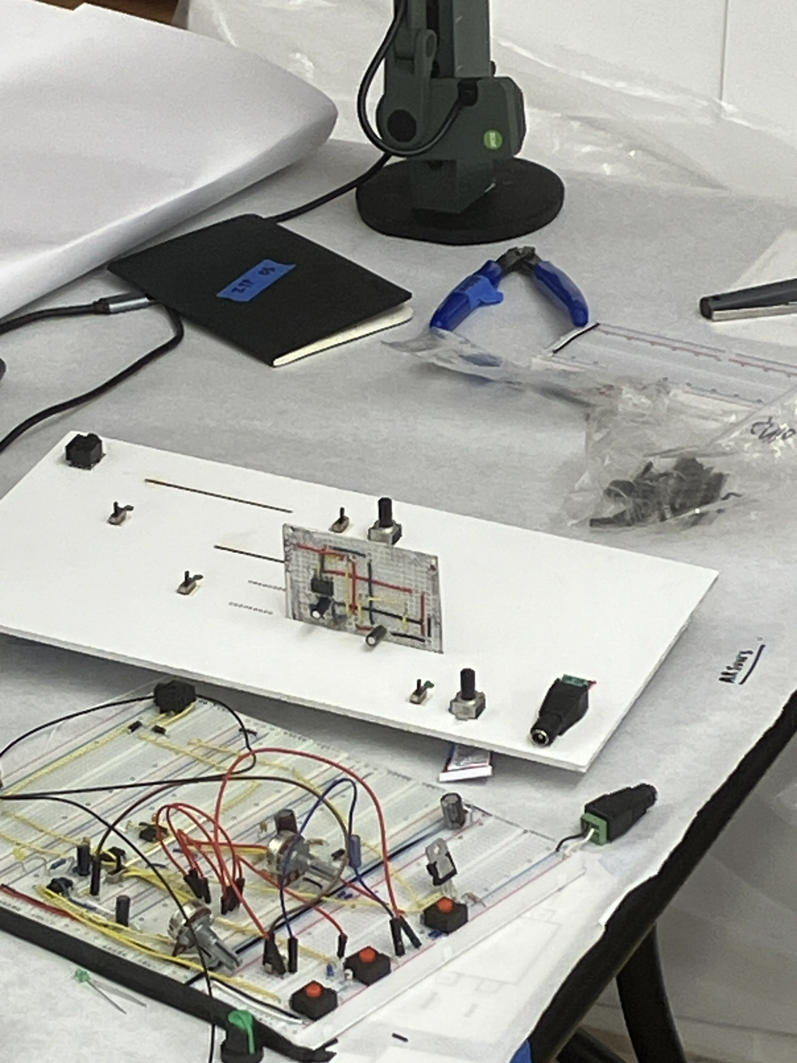
photos:


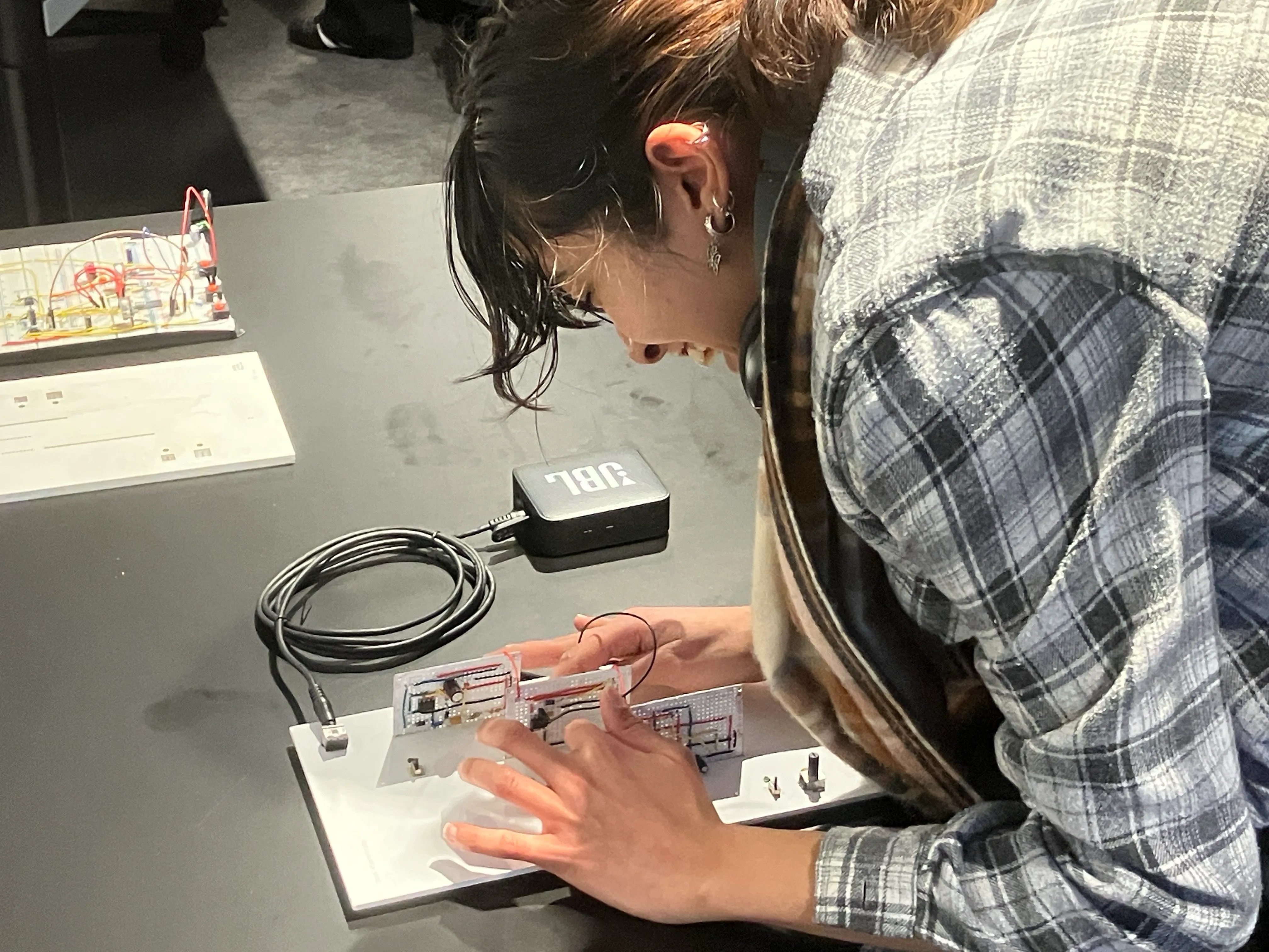
playtest:
video showing people interacting with it: https://youtu.be/-MBHHO_WjQQ
i initially thought that my project was a failure. but something surprising happened. summer discovered that if you touch the circuitry, it would generate different sounds (since you complete the circuit in different ways). that became my saving grace, and i changed my instruction from then-on to be: this device makes sounds. touch whatever you want on the board. people obliged.
at the end, we discussed a little bit about interaction. my project had more room for play, and it ended up being an exploratory interface. it also, surprisingly, led to sustained interaction.
galt made an interesting connection to finite & infinite games — there were some experiences with a clear beginning, middle and end (and often ended with you ‘winning such as valerie & raven’s’); whereas others were more infinite (such as shentong’s and mine).
i wondered about sustained interaction in that discussion. i thought: wasn’t it just a combinatorial problem? an interface that has many possibilities for inputs, with fast-feedback, will often result in sustained-interaction; because people love ‘figuring things out’. but i wonder how much of it would sustain outside the premise of “go try someone’s project”.
as i think more about this, the goal is not sustained interaction (otherwise you fall into traps of making a facebook). the goal is to make contextually-sensitive interactions (sustained when it must, easy when it must, ‘intuitive’ when it must, and jarring when it must). related to my principles as a creator.
251211:
octavio said that i had fabricated it well. he was right — i didn’t give myself enough credit for making it look neat. i wish i had planned it before (but that’s going to be a recurring problem for me this year).
references:
david rios shared these:
- https://www.electronics-tutorials.ws/waveforms/555_oscillator.html
- https://www.instructables.com/Schmitt-Trigger-Synthesizer/
- forrest cookbooks: https://research.ebsco.com/c/srayvq/ebook-viewer/pdf/w2c446nmsr/page/pp_19
et-cetera: