i hadn’t done the serial-communication lab in the previous week, so i did that this week.
realised that an arduino is a development board — i write firmware for the board. my firmware is compiled into machine-readable code (binary), and sent to the arduino-bootloader. the bootloader facilitates the installation of the firmware onto the flash-memory of the controller.
then the controller goes sequentially through bytes of memory (0x0000 … ), and the cpu sends electricity to different parts (is what i gather).
i didn’t understand this:
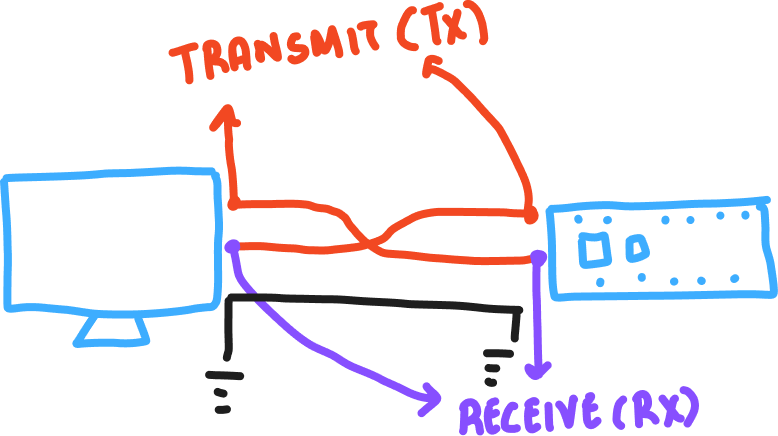
As you might guess from this diagram, both devices also have to agree on the order of the bits. Usually the sender sends the highest bit (or most significant bit) first in time, and the lowest (or least significant bit) last in time.
if the microcontroller simply sends highs & lows (binaries), what is the ‘highest’ or ‘most-significant’ bit.
tom’s response:
In any number, the digit which represents the highest value is the most significant. So, for example, in the number 32,768, the most significant digit is the 3, because it represents 30,000. The 2 represents 2,000, the 7 represents 700, and so forth.
this was interesting:
The advantage of a USB-native microcontroller is that they can also be programmed to behave as other USB devices, like MIDI, Mouse or Keyboard.
i wonder how.
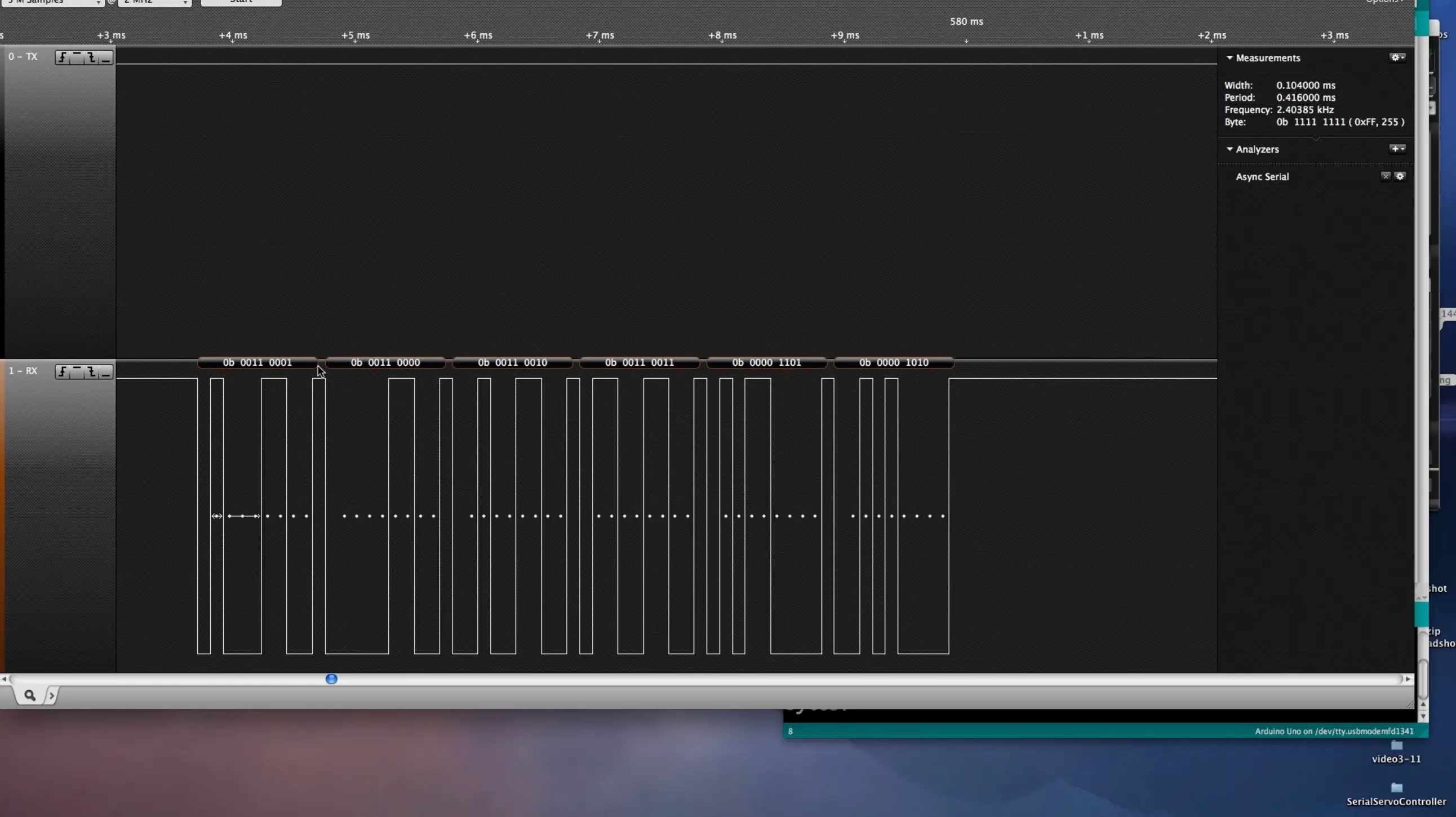
tom connects a ‘logic-analyser’ in one of the videos. we don’t have it in the shop.
i hooked up a photoresistor, and tried to read values in different ways.
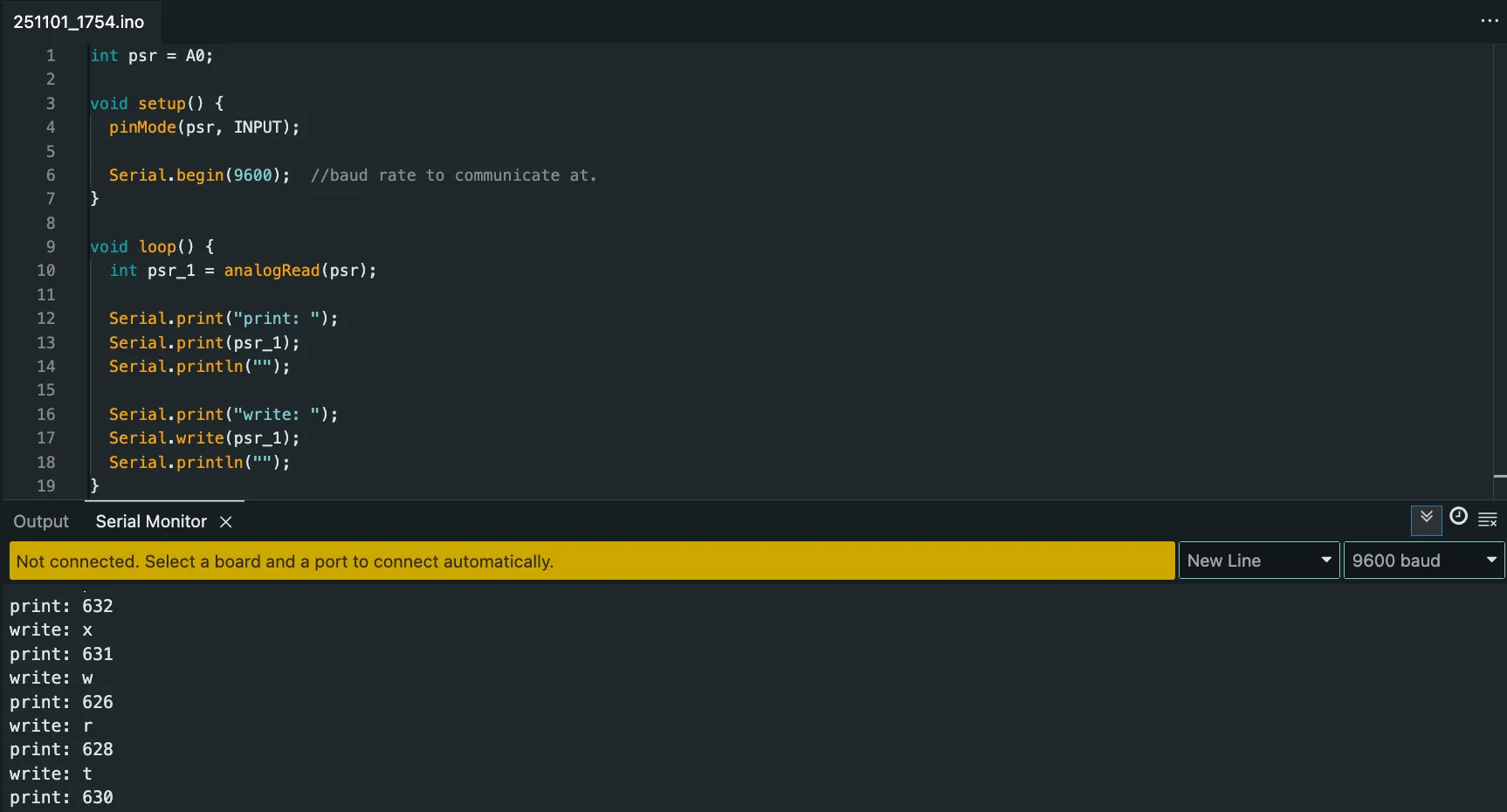
i understand that ‘print’ converts what the arduino receives into numbers that i care about.
i decided to go simpler, and see only what a button-press prints out in different formats.
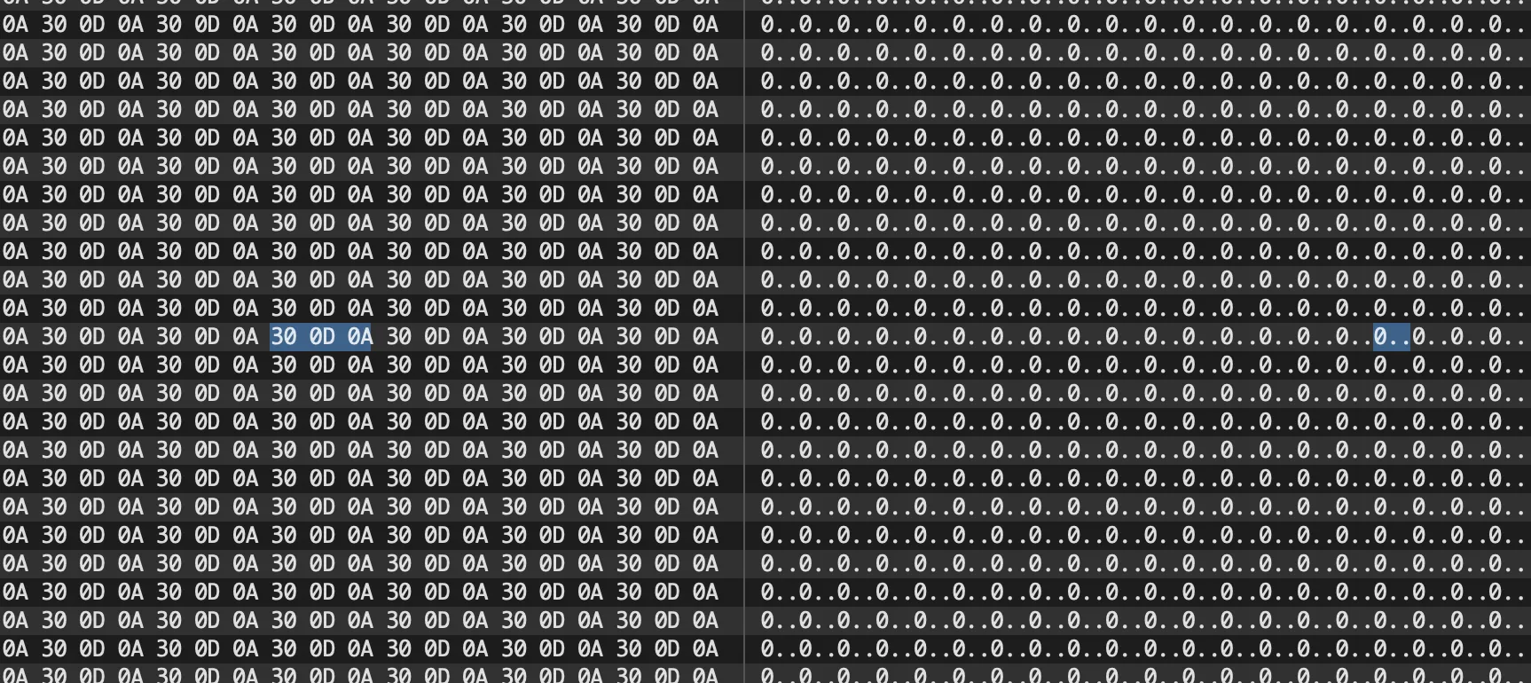
the image below tells me that a zero is 30 in hexadecimal, and a period (+ perhaps a line break) is 0a.
i then decided to understand what the hell these numbering systems are via this: https://www.youtube.com/watch?v=ZL-LhaaMTTE
then watched this: https://www.youtube.com/watch?v=FFDMzbrEXaE
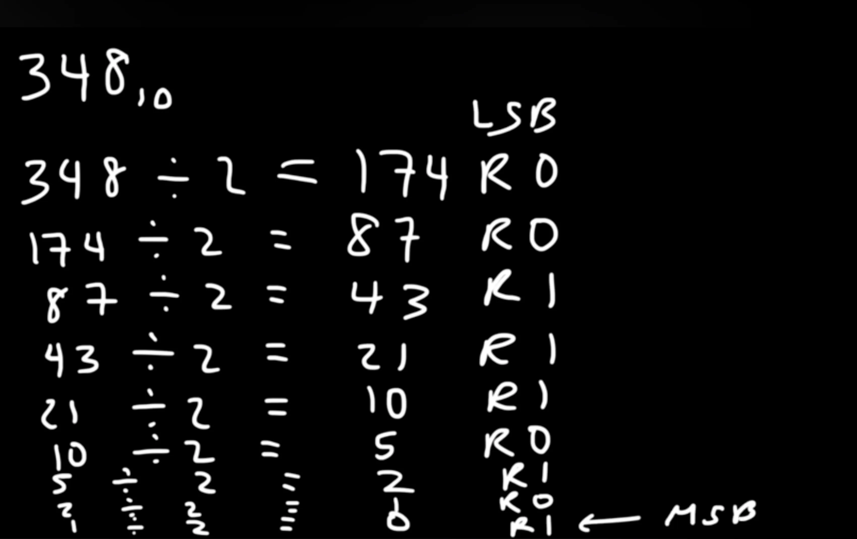
^ this shows you how to convert decimal to binary by successive division. from the bottom (most significant bit) to top (least significant bit).
for the same circuit as before, Serial.write sends information in a different format.

chatgpt says this:
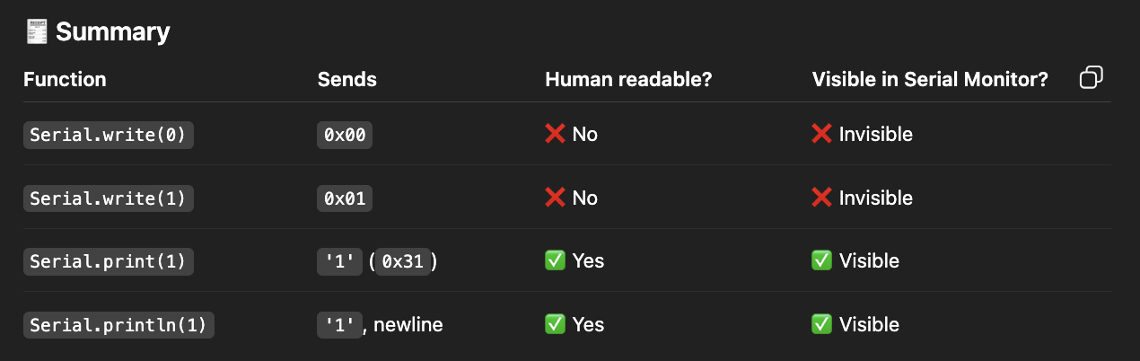
so, from what i can gather: the serial monitor on the arduino-ide is designed to display only a specific format (i don’t know what to call it, but human-readable format (apparently)). i then found Serial.print(), and used it to print values in different formats.
i then realised that i2c is just another protocol. i remember helping duan & her partner with their motion sensor which used i2c (via the arduino’s scl & sda pins). i now understood how that actually worked.
if i understand this correctly, the arduino sends bytes. bytes are then converted into decimals (somehow) — i believe this has to do with the frequency of communication (it expects a certain number of values before it makes sense), which are then converted into characters to be able to print in the ide.
got p5.serialcontrol to work for a button press.
p5 doesn’t natively support serial-connection. so, the workaround they made was to use a standalone application that then provides a websocket connection to p5.js.
websocket: https://www.youtube.com/watch?v=ub7RVLSn3mc — essentially a way for a server & a client to partake in real-time two-way communication via a certain protocol. instead of an api, which requires you to request something, a websocket is a connection in perpetuity (until you close the websocket).
the serial-port library makes a serial-port object in p5, when you make an instance:
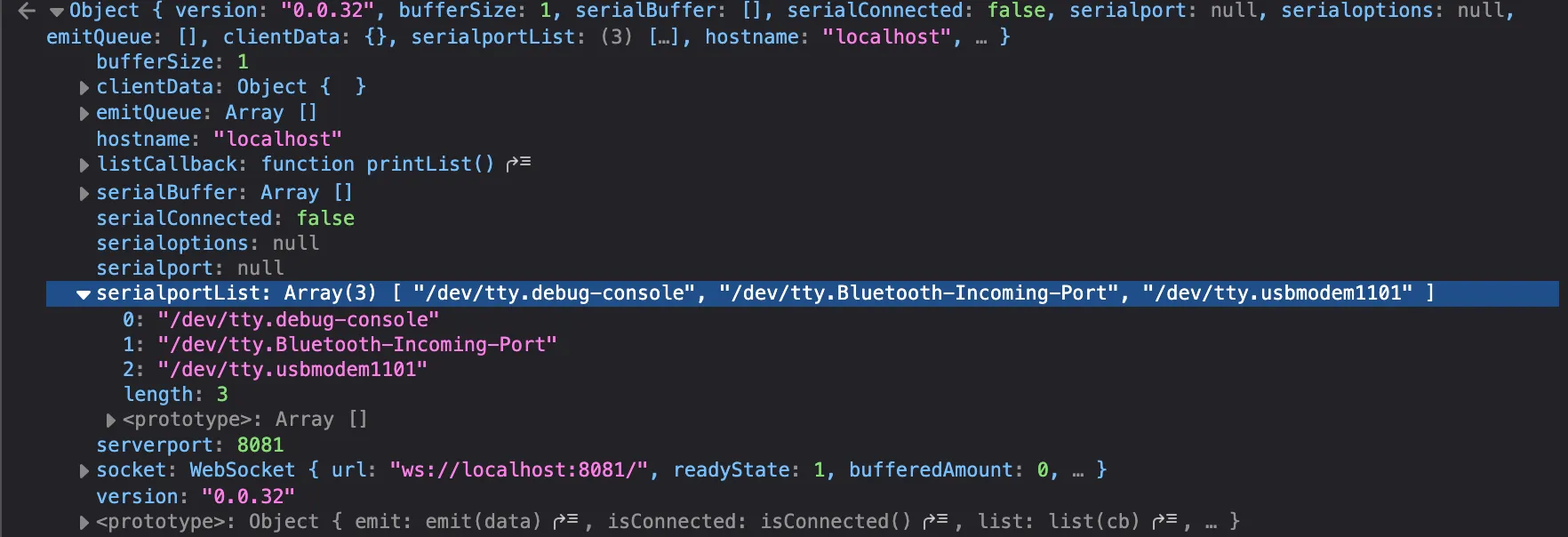
i couldn’t get it to connect.
i have many questions:
- p5serial-port makes a connection to ?
- how do you know the default agreements? meaning how do you know whether the serial monitor of a piece of software will show what type of data, how they’ve agreed on what is high / what is low, et-cetera? does the arduino dictate this? or does the program? can we change these agreements?
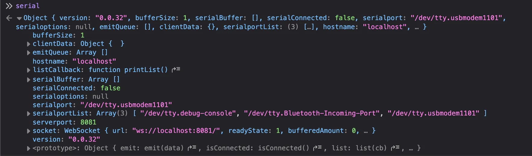
251106:
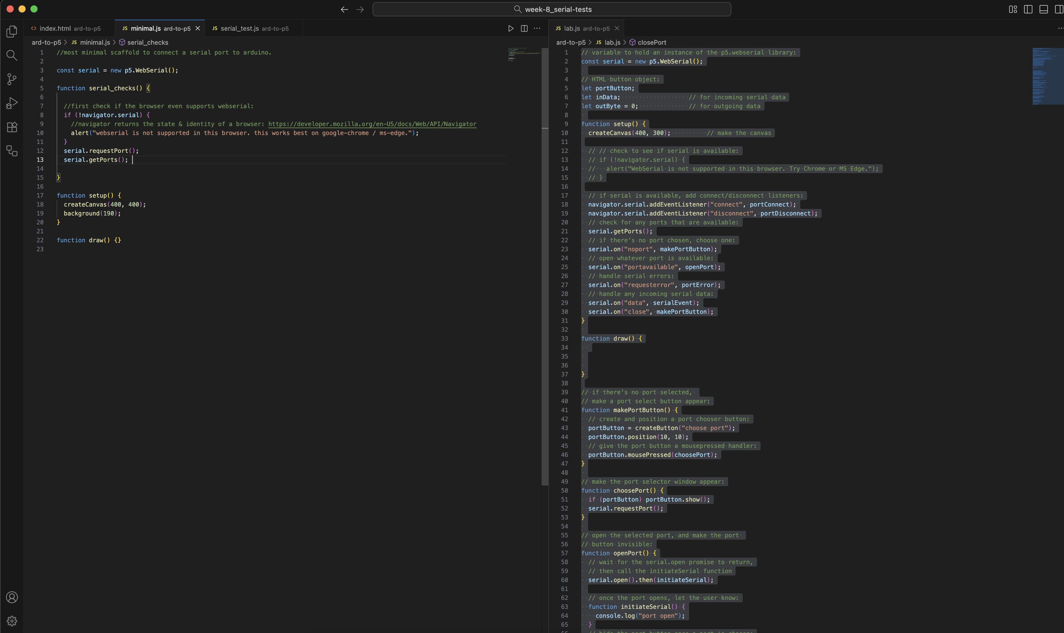
i got serial communication to work. i have no idea why it magically decided to work, but it does now. finally, i can make progress with the labs.
serial works on listening for events (change) & callbacks (what to do if changed). we have:
- noport (no selected serial port)
- portavailable (port becomes available)
- data (new data comes)
- close (serial port closed)
- requesterror (something went wrong when requesting for a serial port)
- connect / disconnect (physically connected or disconnected)
i then tried to write a reusable function to allow me to simply pass in a port-name; so that i don’t have to copy paste all of this code over & over again.
but this was a bad attempt. it’s difficult to do so; since everything relies on callbacks & events.
251110:
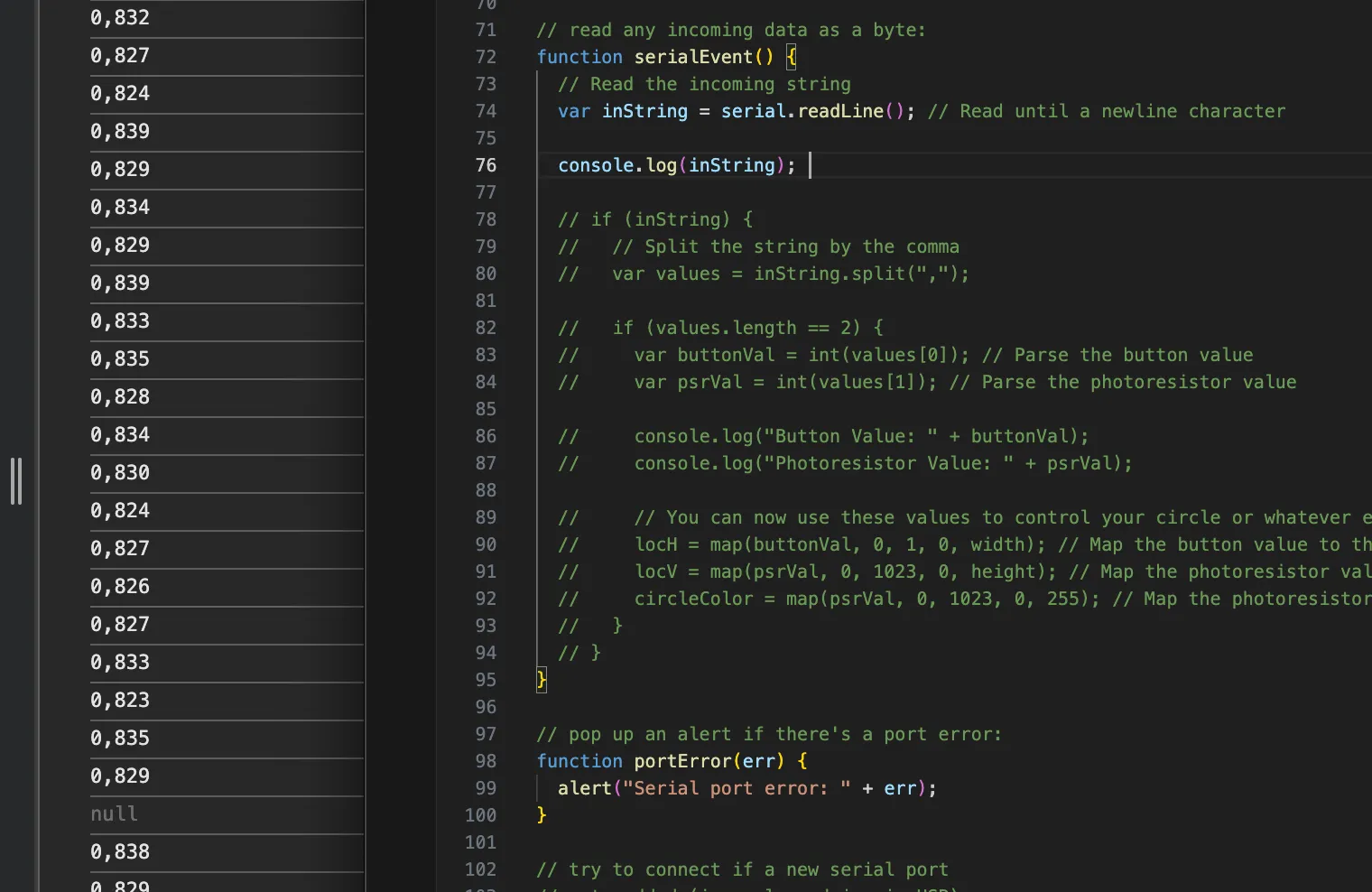
i understood that read_line reads until a newline character is detected. you can then parse the data, since you know the range that p5 is going to receive.
i thought about making something with serial-communication, but decided against it. i know that i can refer to this / make it work when i need to — such as when i need to think about a new input device.
however, for now, i decided to spend my time elsewhere.