started a midterm-log, reflected on the ask.
learnt about relays. realised that i was using a relay all along; which nikolai gave me:
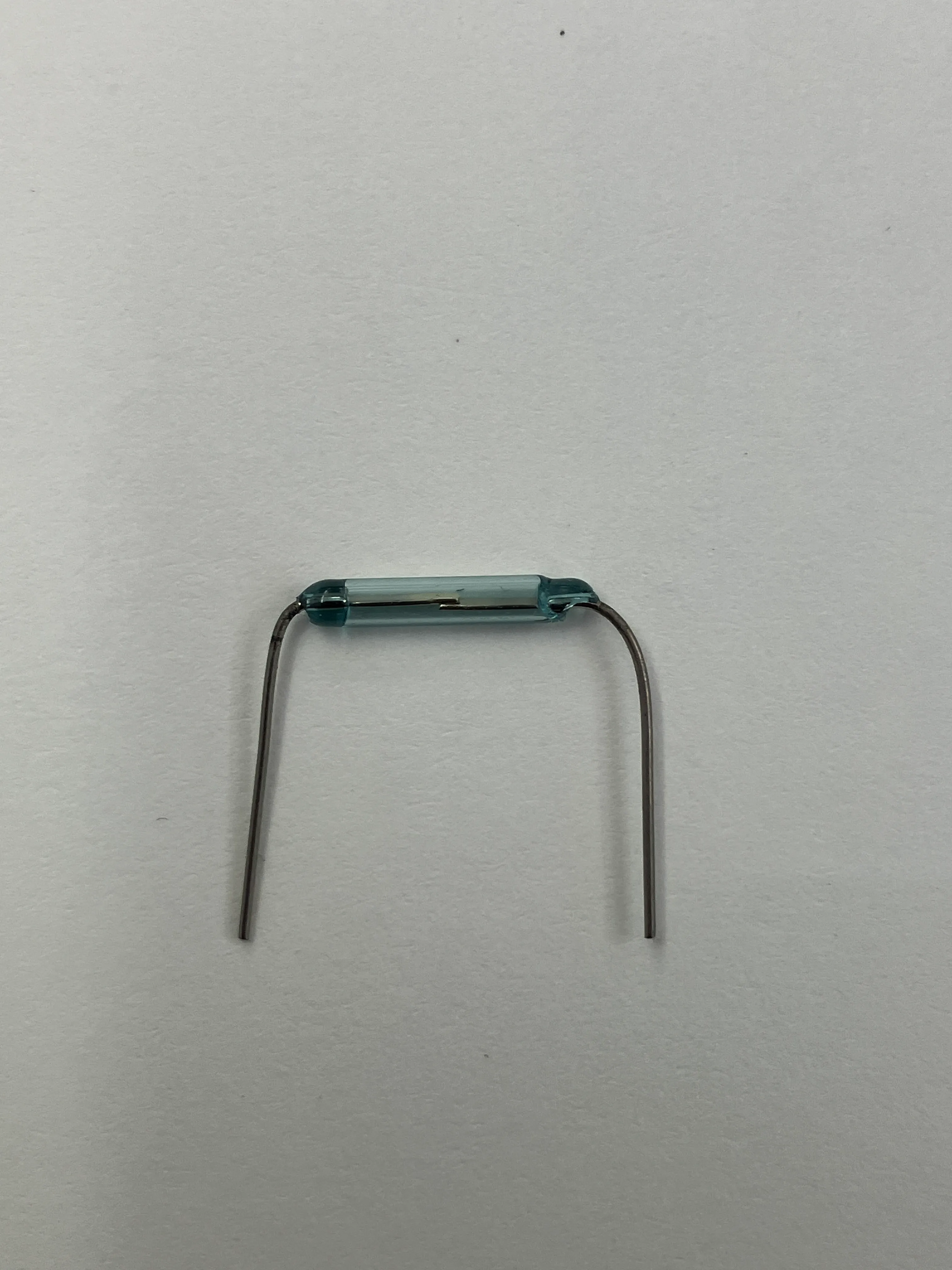
relays make use of the fact that electric current produces a magnetic field (see electromagnetism), and allow two metal pieces to connect together, when voltage is passed through a source (much like a transistor). relays do this mechanically, while transistors do this electronically (a switch).
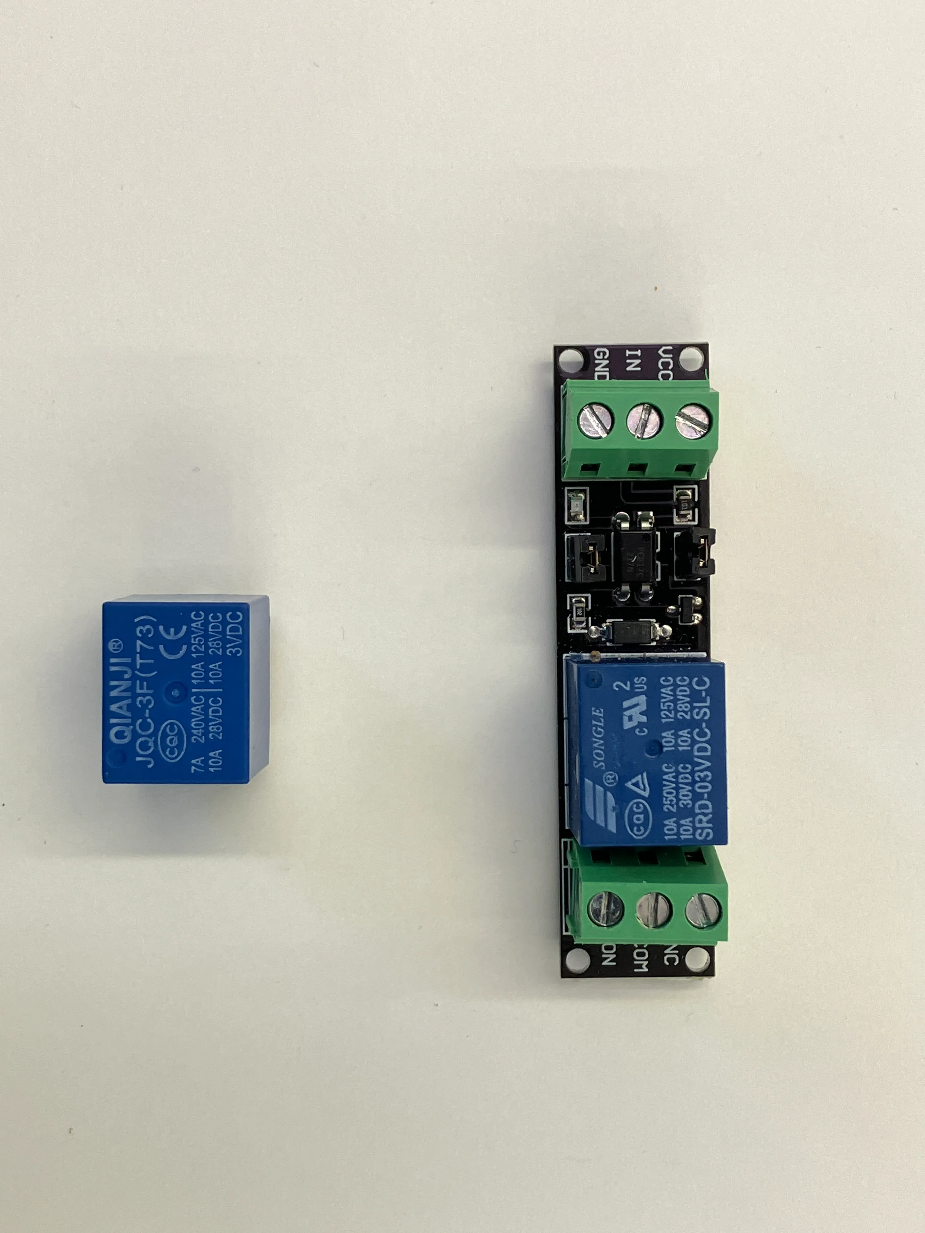
i got a relay from the shop. no one had the pins for it though, and the negative-ends of the jump wires don’t fit.
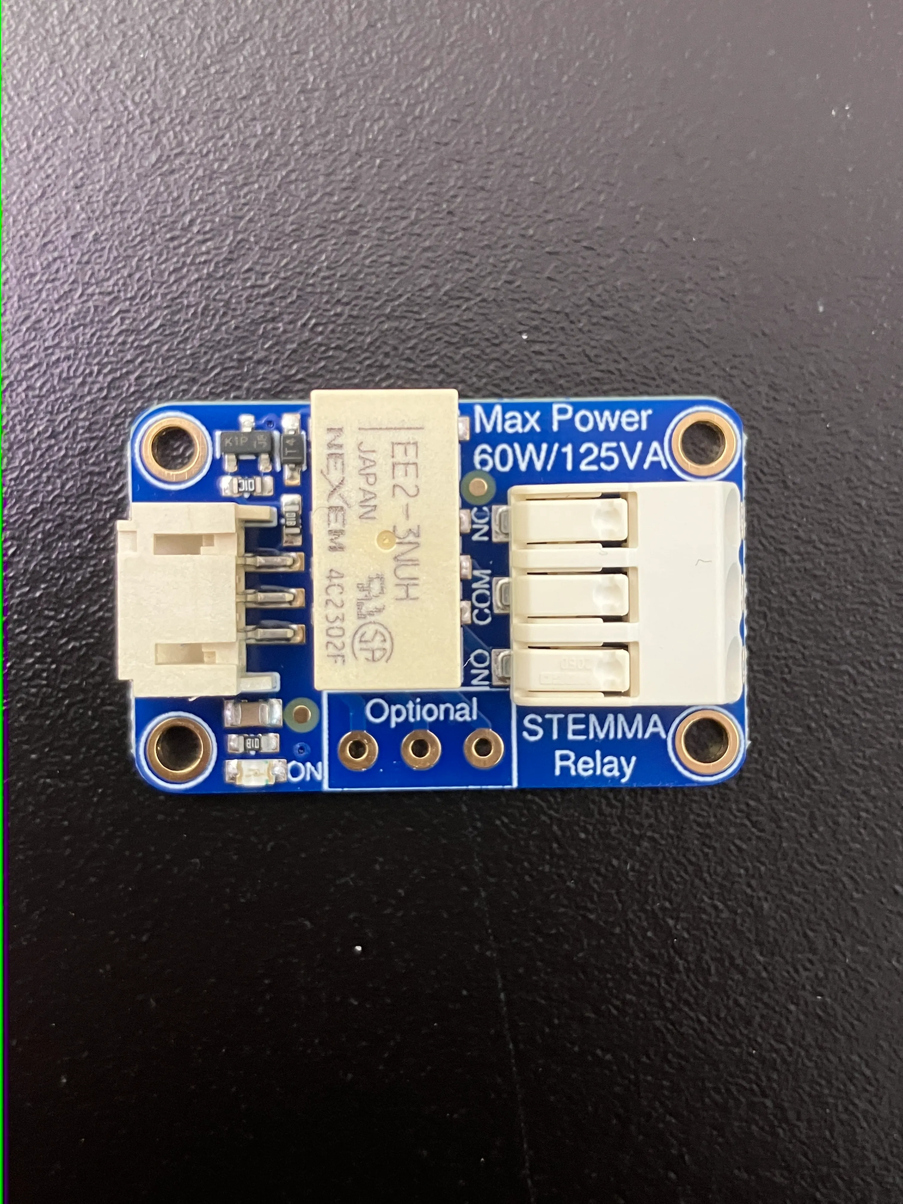
i went to david rios wondering whether he had the pins for these. he didn’t, but he was kind enough to give me two of his relays.
understood different types of actuators:
worked with a linear actuator. realised that i need to reverse the polarity to make it go backwards. that was interesting to me.
i’m going to try and build a circuit that performs sort of drawing.
i first thought about how i could alternate current. i figured that i could do this with two transistors, but then later read about h-bridges.
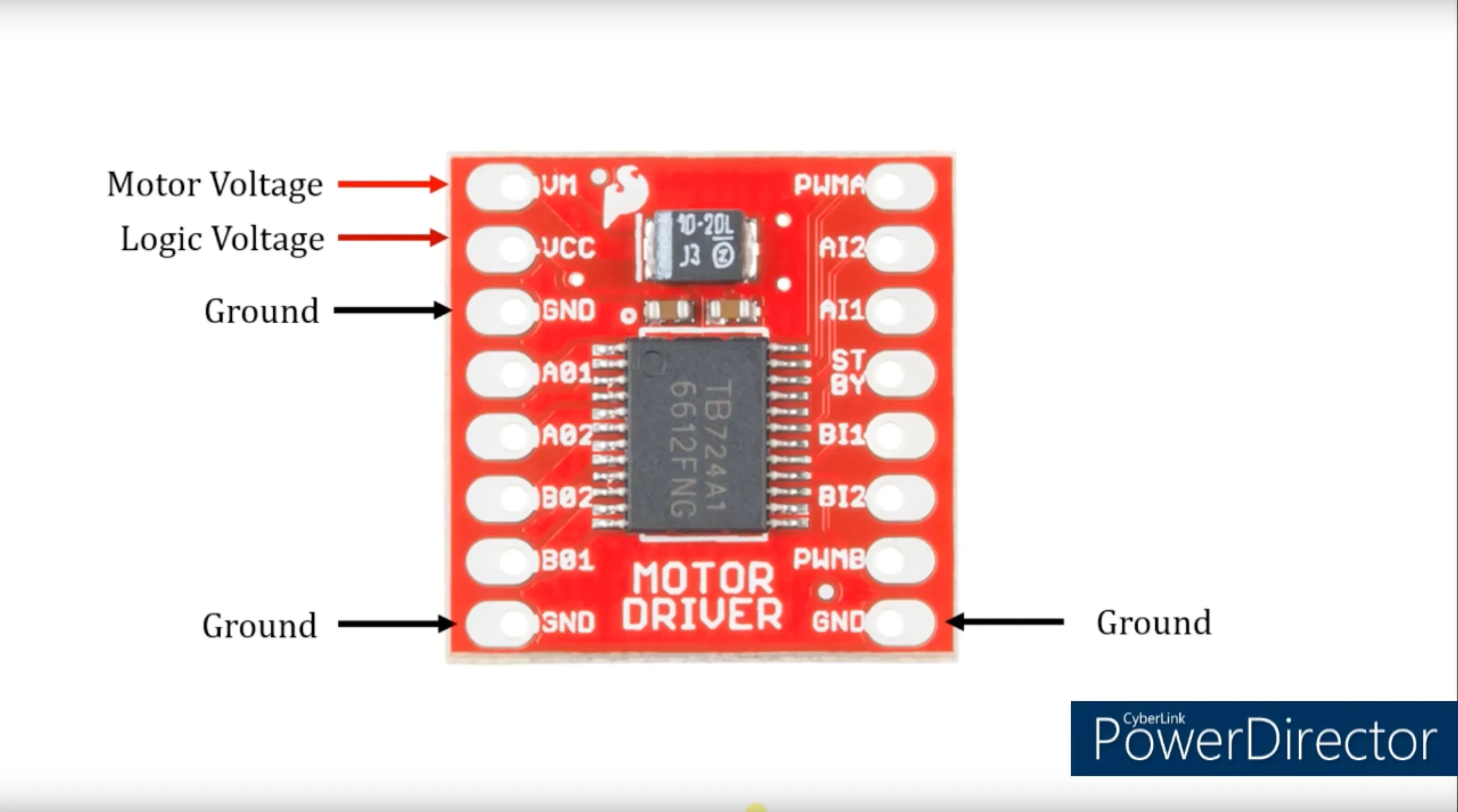
soldered the motor-driver. cody helped me understand what good solder looks like. apparently, i’d pass in his shop.
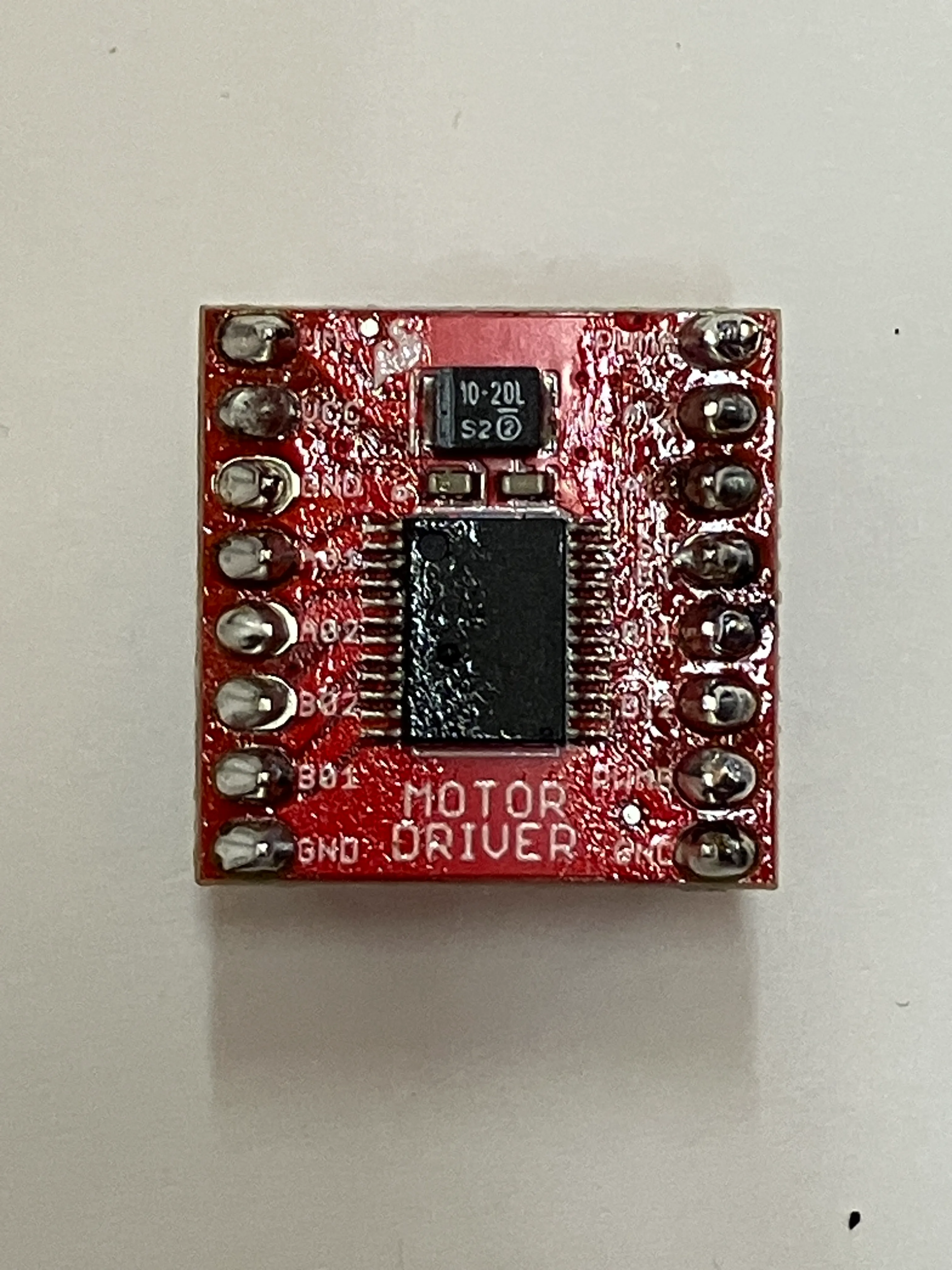
motor drivers have logic gates inside them, that open or close based on certain conditions.
that’s fucking beautiful.
source: https://cdn.sparkfun.com/assets/0/1/b/b/3/TB6612FNG.pdf
source: https://knowledge.ni.com/KnowledgeArticleDetails?id=kA03q000000YHvvCAG&l=en-US
i made a circuit, and realised that ‘low’ does not mean off.
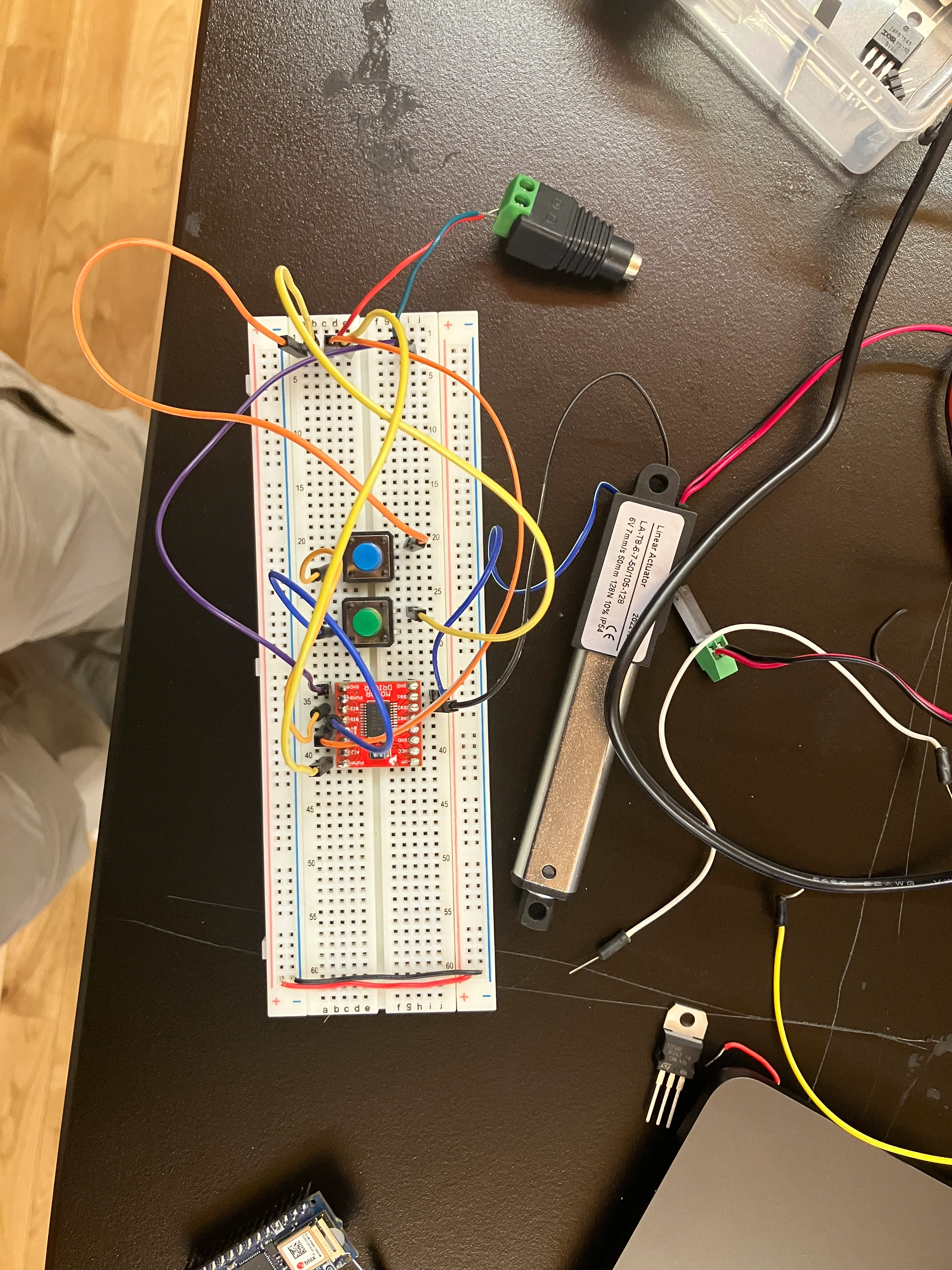
i made a linear actuator move with a manual h-bridge.
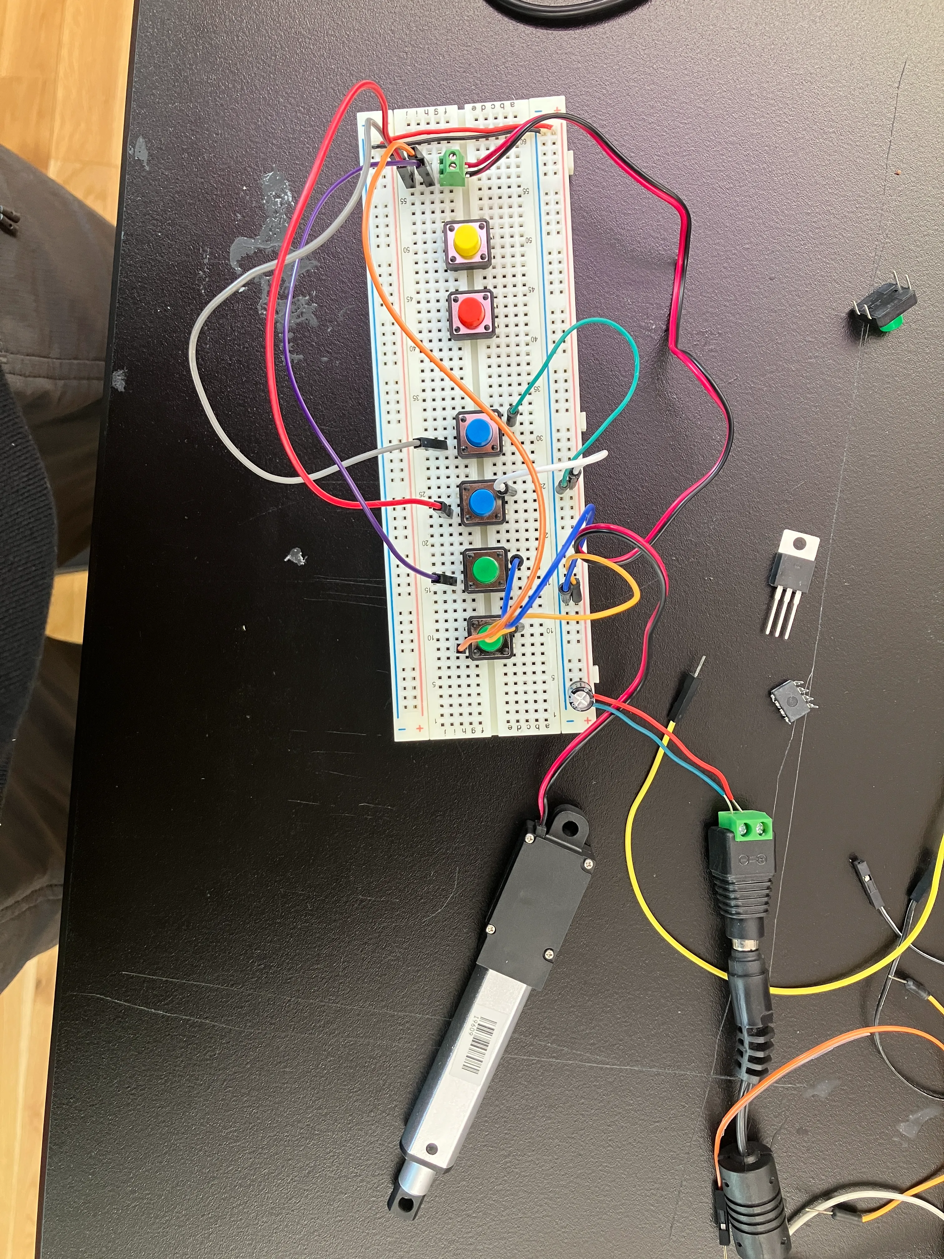
now, i’m going to attach a servo on this, so that people can draw. i will first test it, and then clean up the wiring.
decided to use a stepper instead, so that i understand that more.
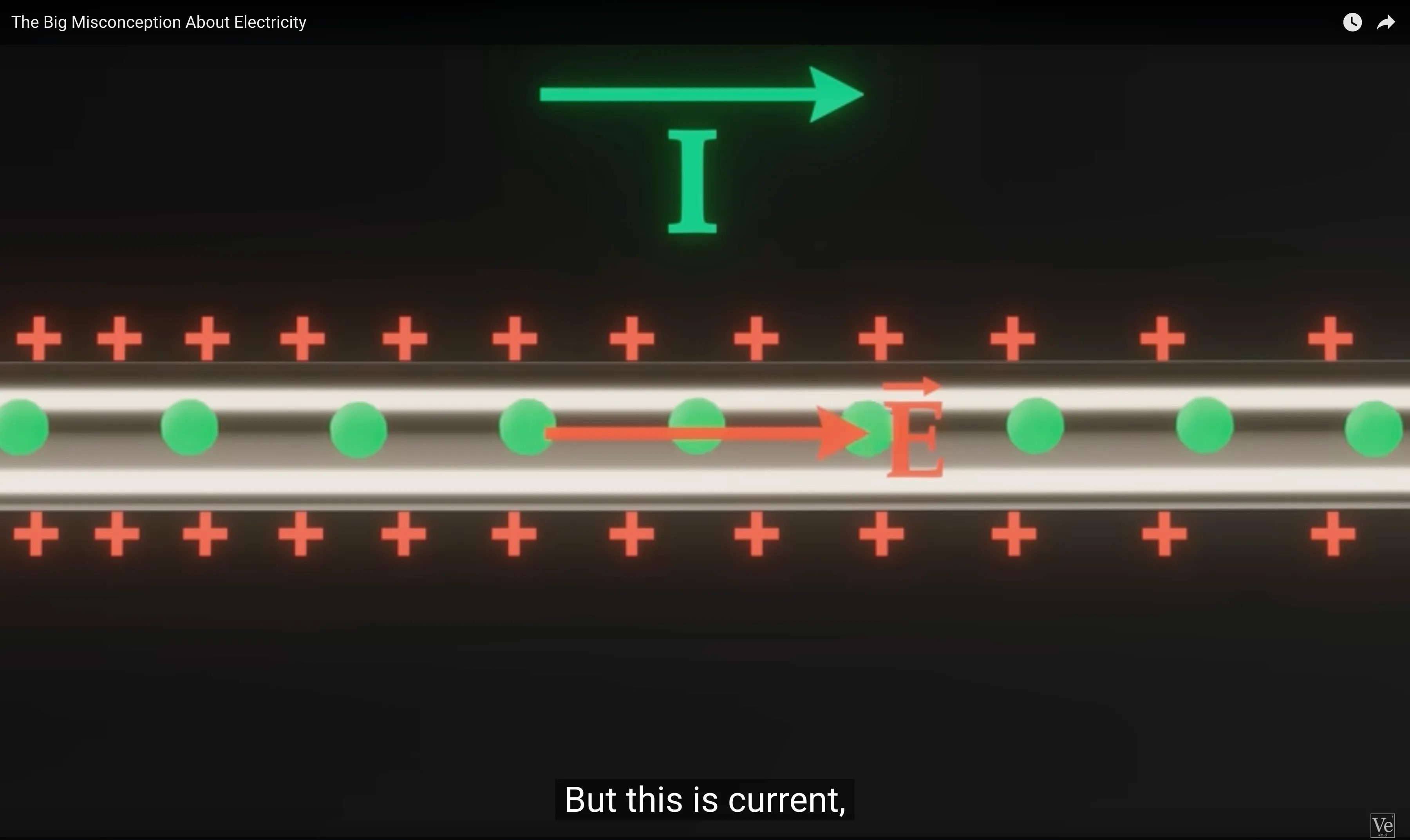
got curious about electrons while having lunch. watched this: https://www.youtube.com/watch?v=bHIhgxav9LY

learnt about drift velocity, also mentioned in practical electronics for inventors.
electric & magnetic fields:
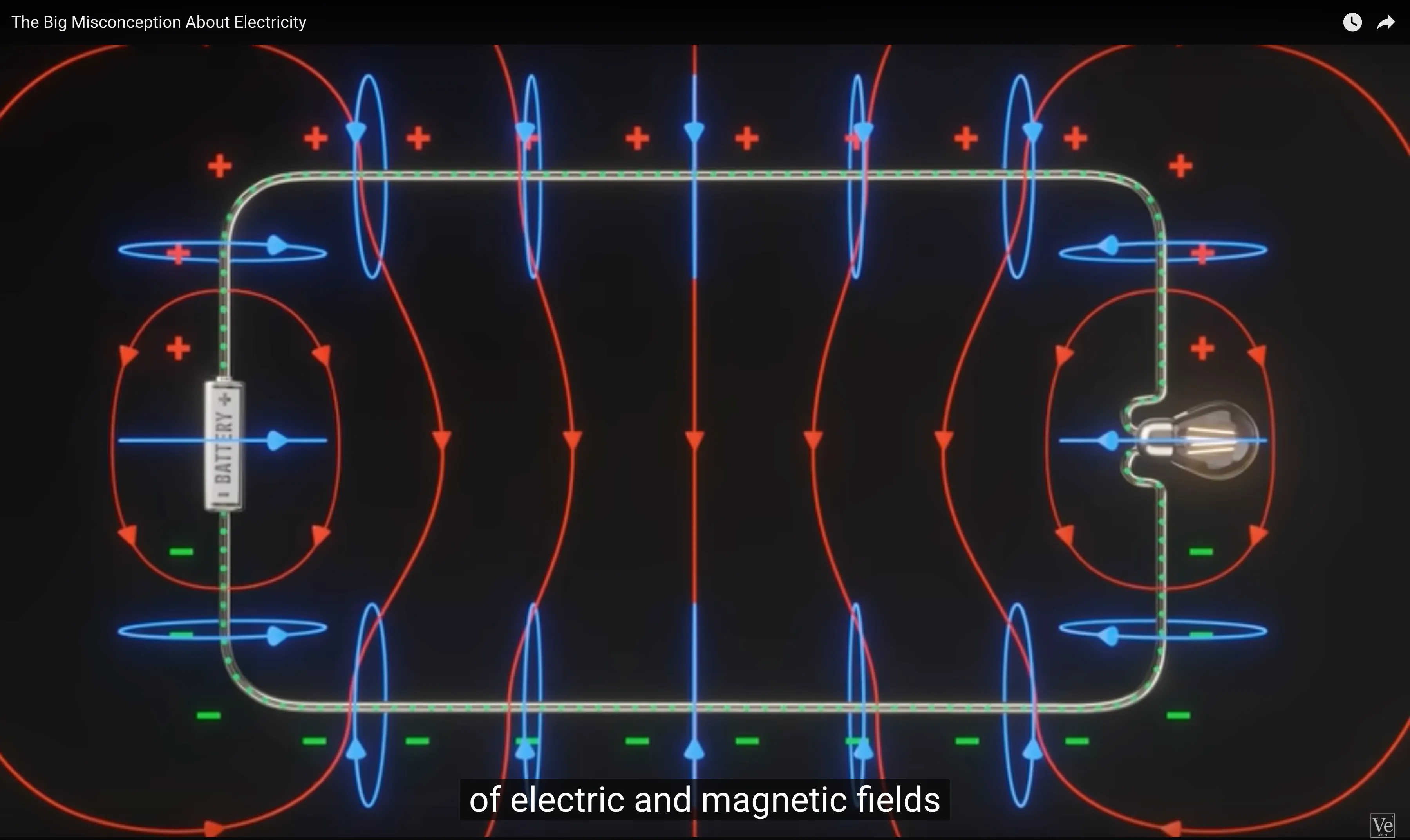
jesus christ.
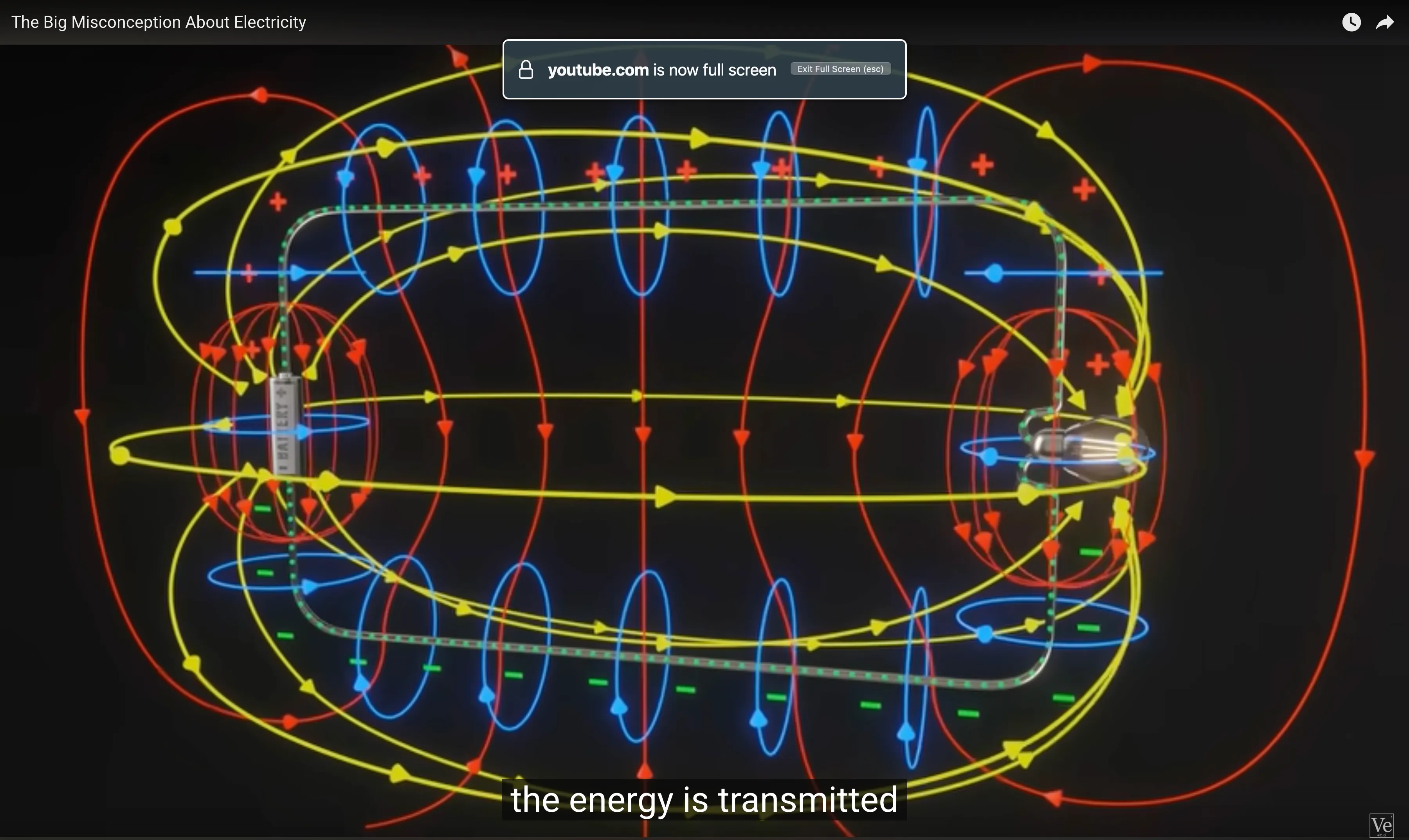
Dr Robert Olsen says: “people think you’re pumping electrons, which is so wrong”.
follow up: https://www.youtube.com/watch?v=oI_X2cMHNe0
put work in midterm-log.
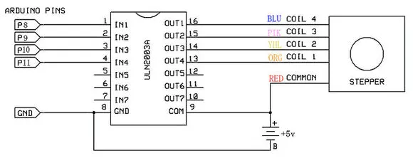
william bet that i couldn’t get the stepper motor to work. i took his challenge on.
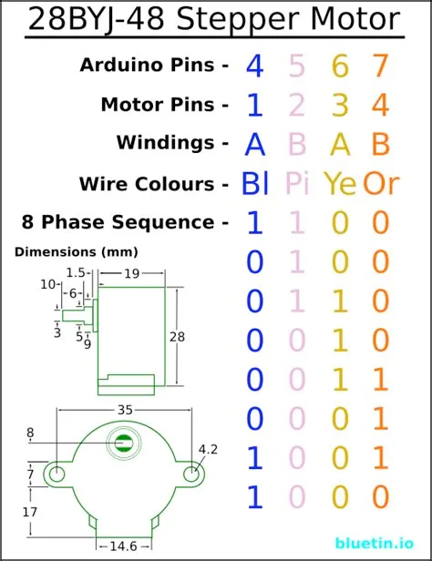
found the datasheet for the stepper here: https://www.datasheetcafe.com/28byj-48-datasheet-5v-stepper-motor/
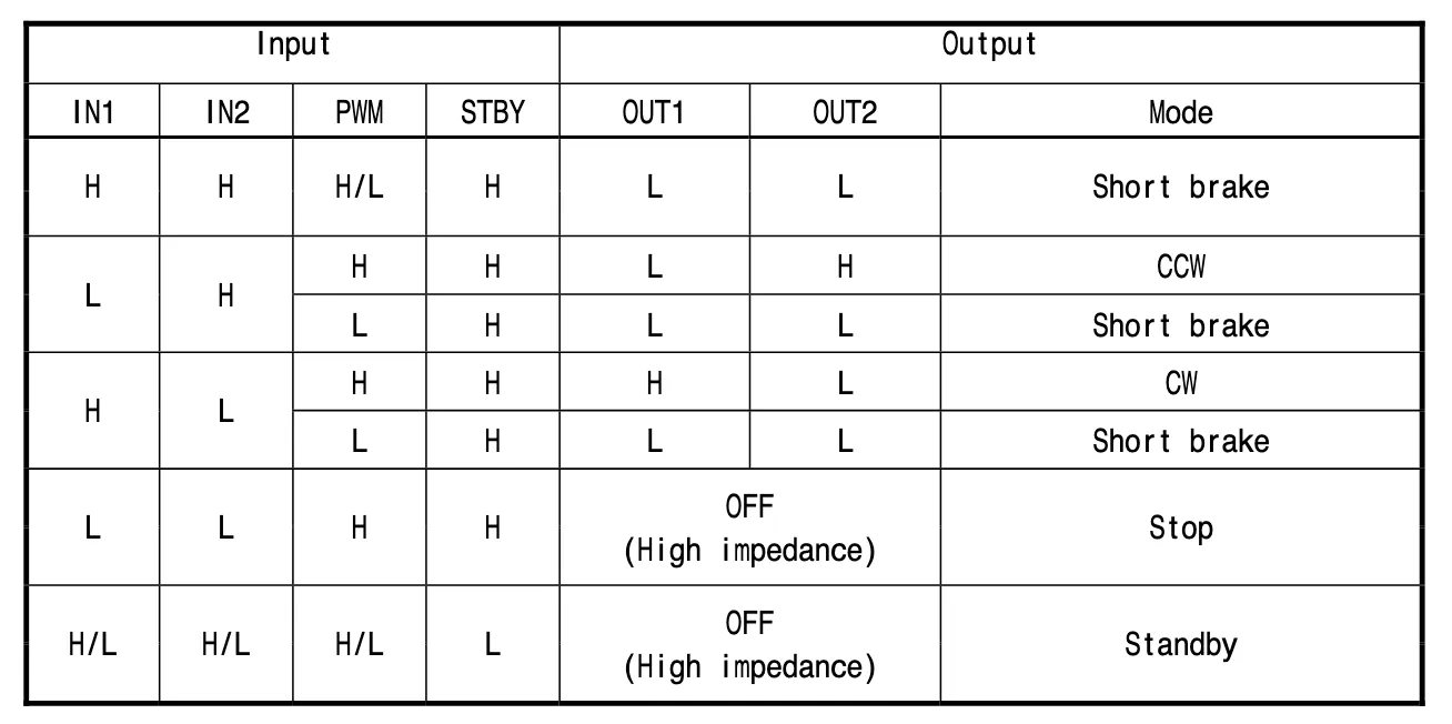
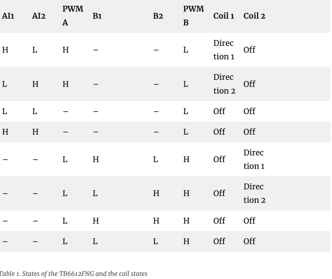
found the truth table elsewhere:
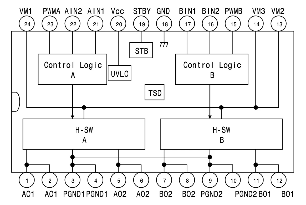
then i spent time understanding the motor-driver. i understood that it’s a dual motor driver.
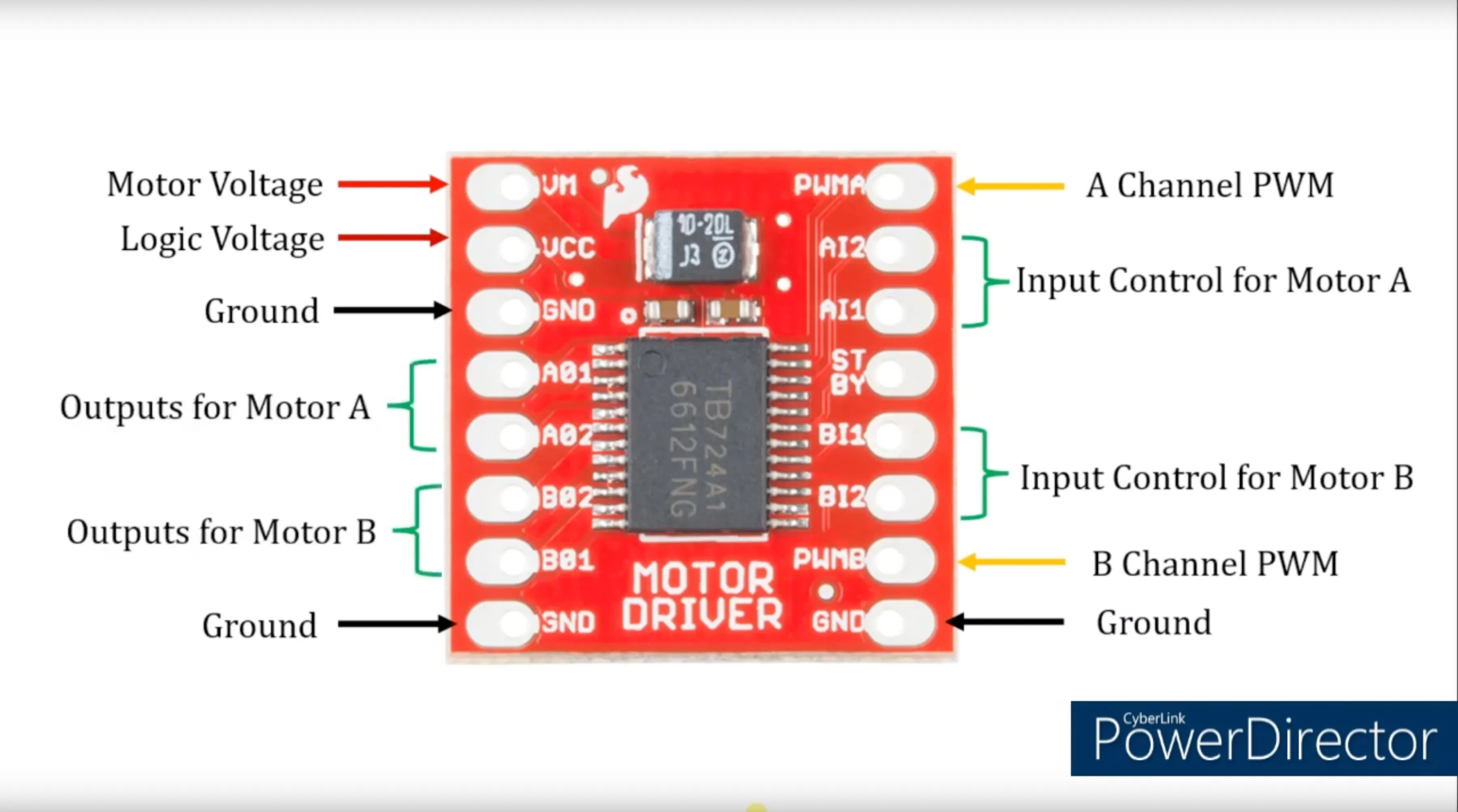
then i used this truth table to write the code.
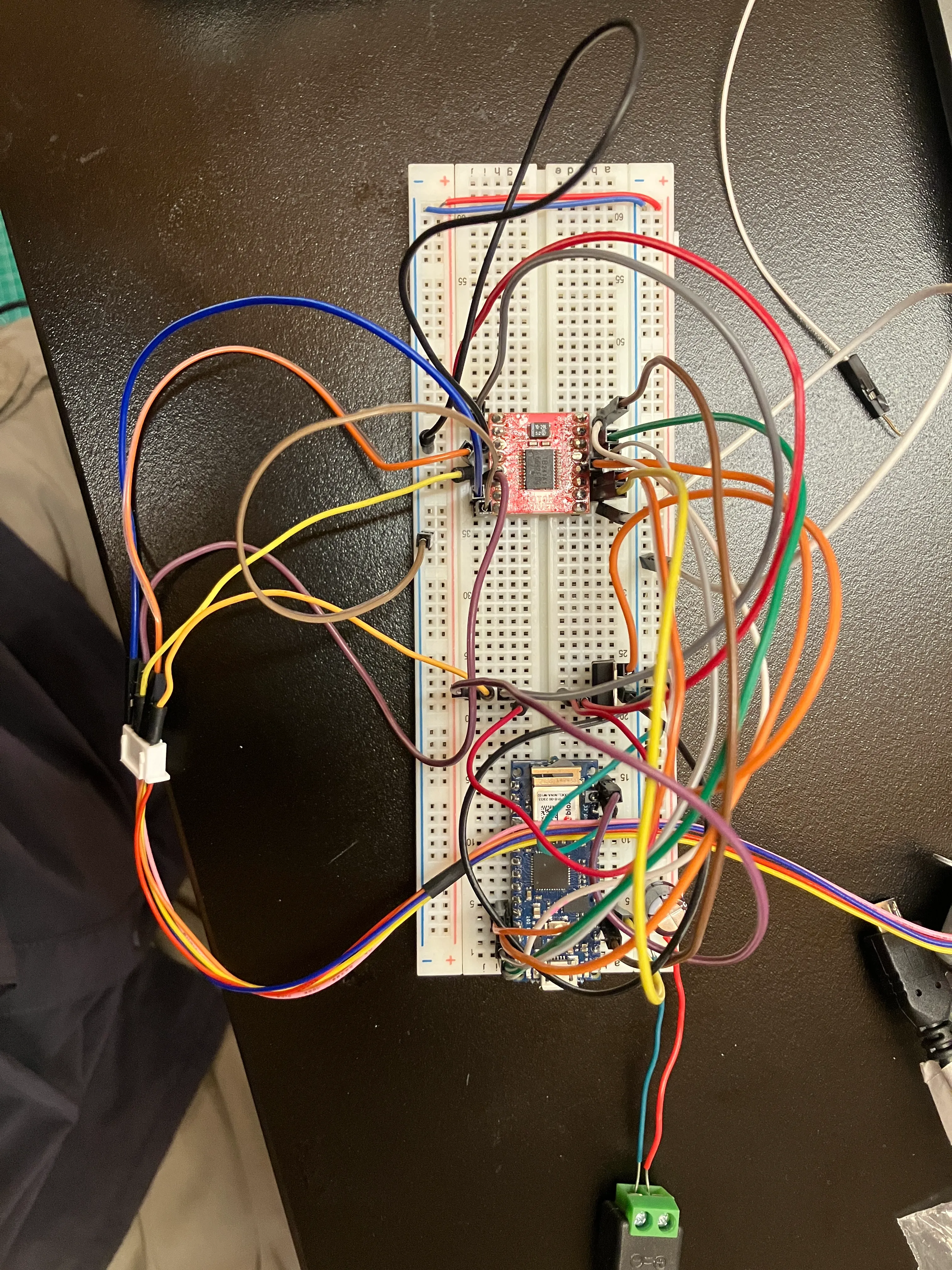
i wired the circuit right. i’m sure. it didn’t work. i measured all the voltages — everything is logically sound.
code:
//stepper with motor driver.

//ref: https://www.youtube.com/watch?v=ksx-AugHlrI

//define global pin-numbers:
int ai2 = 12;
int ai1 = 11;
int stby = 10;
int bi1 = 9;
int bi2 = 8;
int pwmb = A0;
int pwma = A1;

void setup() {
  pinMode(ai2, OUTPUT);
  pinMode(ai1, OUTPUT);
  pinMode(stby, OUTPUT);
  pinMode(bi1, OUTPUT);
  pinMode(bi2, OUTPUT);
  pinMode(pwmb, OUTPUT);
  pinMode(pwma, OUTPUT);

  Serial.begin(9600);

}

void loop() {
  //set standby to high:
  digitalWrite (stby, HIGH);

  analogWrite (pwma, 255); //speed to high.
  analogWrite (pwmb, 0); //speed to low.
  digitalWrite (ai1, HIGH);
  digitalWrite (ai2, LOW);

  delay(1000);


  analogWrite (pwma, 0); //speed to high.
  digitalWrite (ai1, HIGH);
  digitalWrite (ai2, HIGH);

    analogWrite (pwma, 255); //speed to high.
  digitalWrite (ai1, LOW);
  digitalWrite (ai2, HIGH);

  delay(1000);

}