testing multimeter:
couldn’t get multimeter to beep, as said here: https://itp.nyu.edu/physcomp/labs/electronics/
tried two multimeters. but i know they’re working, because matt & i tested it on an active circuit.
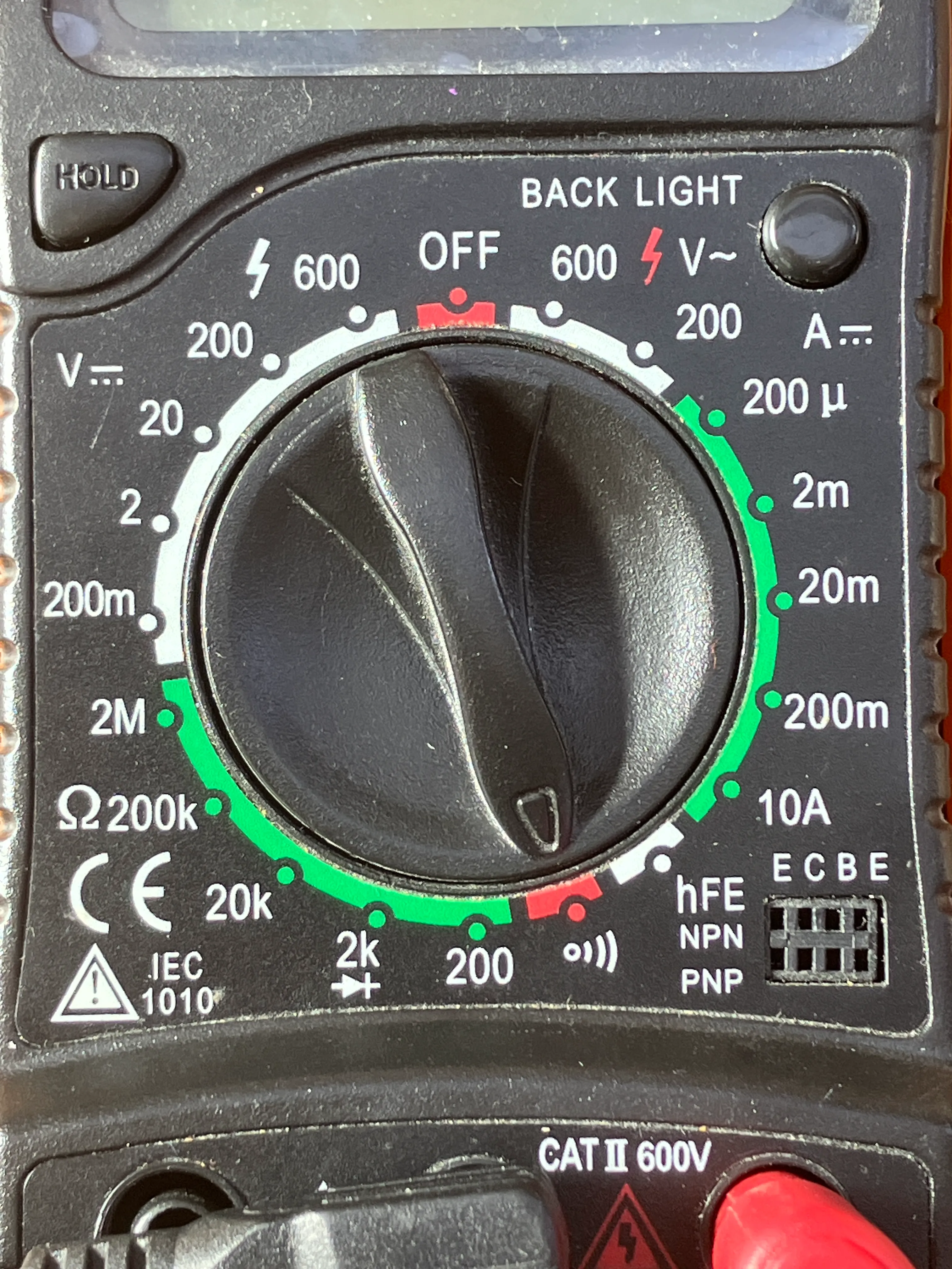
i asked tom, and he told me that i was using the wrong mode. the dials on the multimeter select different modes. for continuity, you want to put the dial on continuity.
what’s inside a jumper wire:
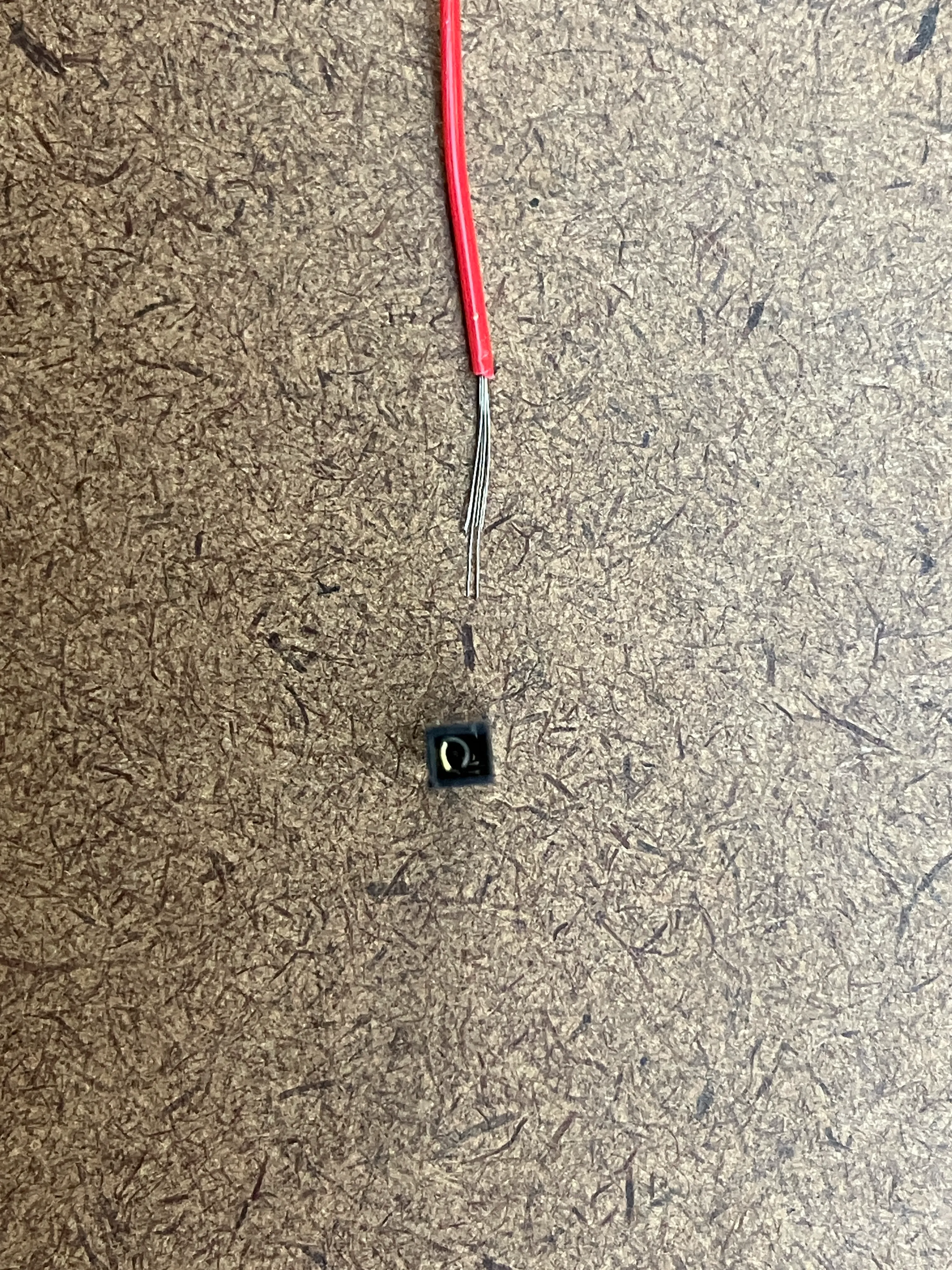
broke a jump wire. became curious about what’s inside a jumper wire.
https://en.wikipedia.org/wiki/Jump_wire
it seems like it’s made from some kind of metal inside, and an insular layer outside. there is a fragile pin, that is then used to connect to breadboards.
checking for continuity on a breadboard:
i wanted to see if i could check continuity on a breadboard.
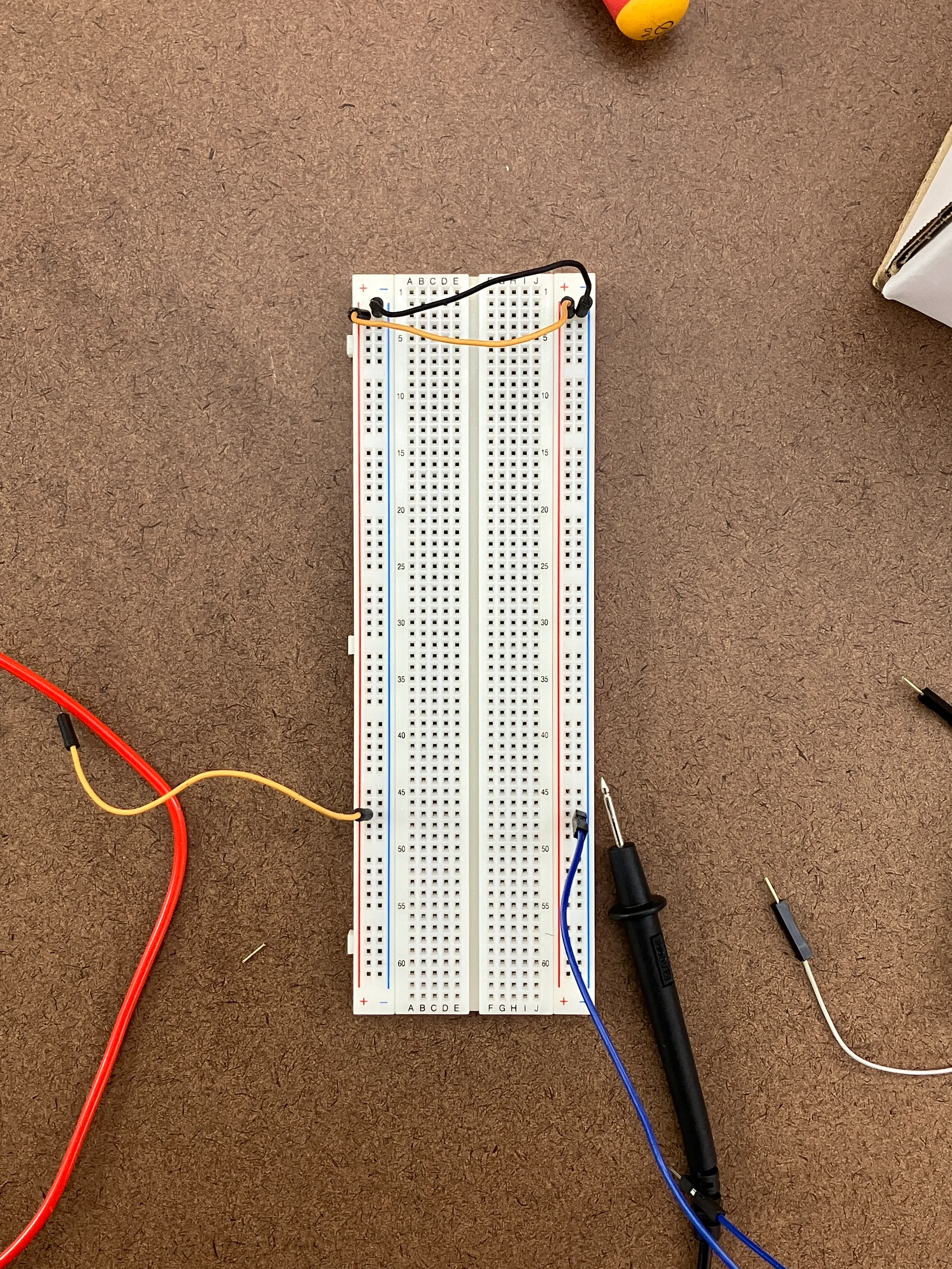
however this didn’t beep as it was supposed to. i can’t figure out why, and will ask the p-comp help-desk today.
update: 250904+1539:
octavio & audrey helped me understand why this was happening. the positive & the negative never meet (although i assumed that they meet in the multimeter). i still don’t fully understand this, and will ask tom in class.
checking power supply from a dc outlet:
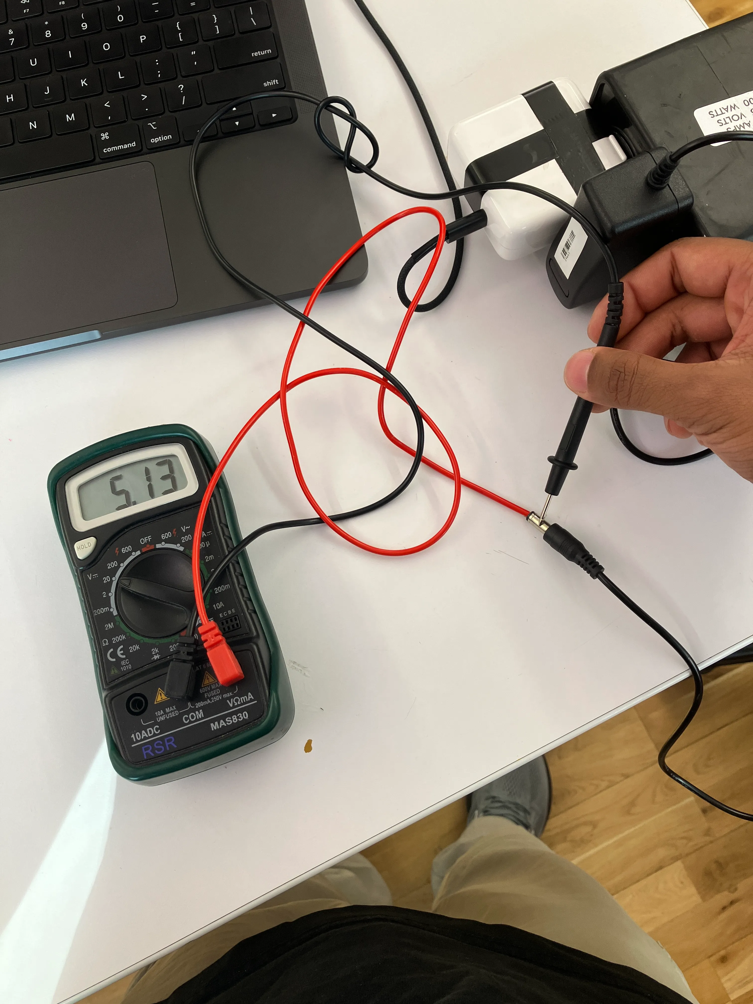
used a multimeter to test power-supply from a dc-power-supply.
powering an led with just dc power supply:
realised that we aren’t really using the arduino right now. so, used dc-supply direct to power an led.
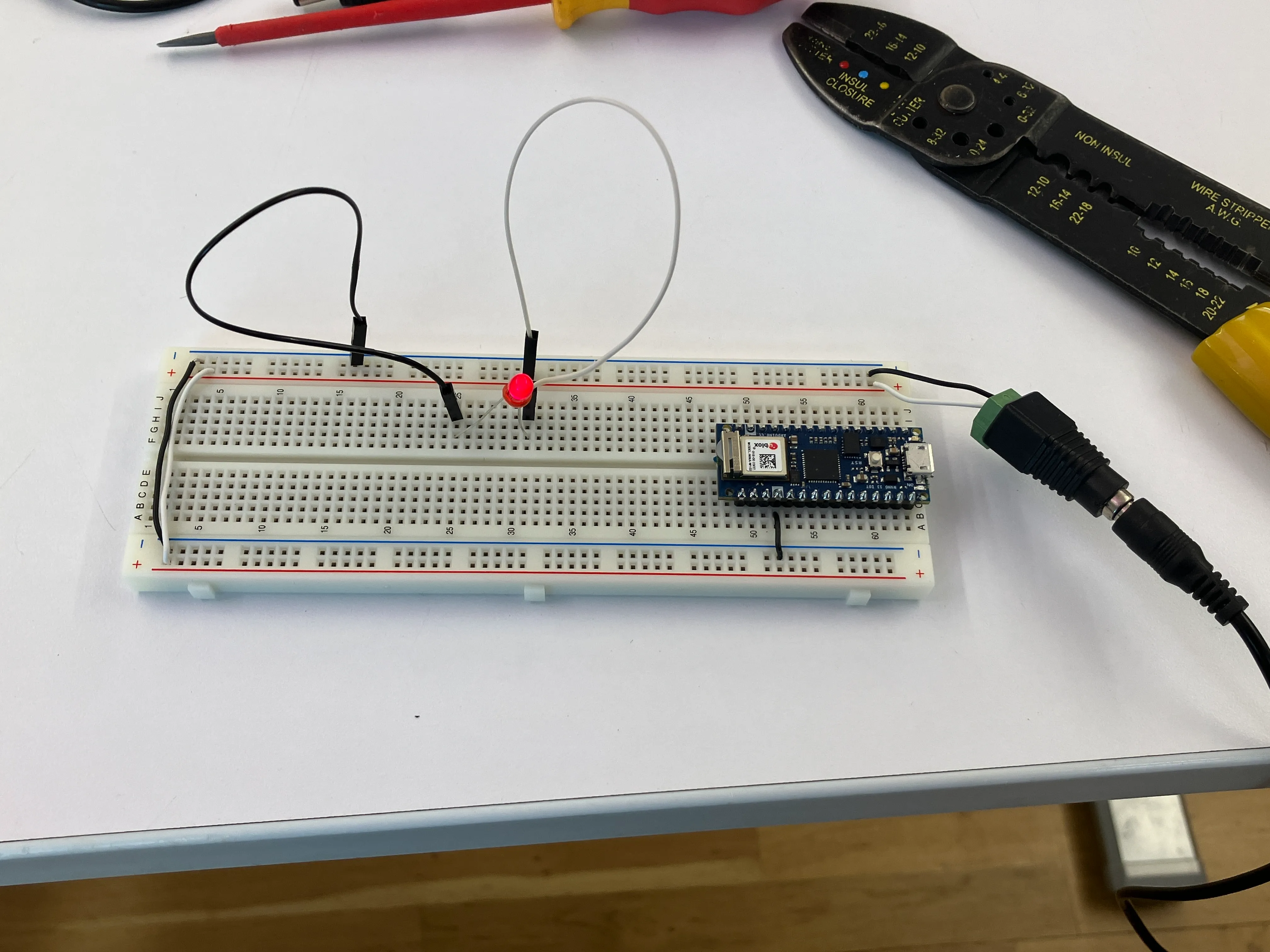
that led stopped working. always use a resistor.
understanding resistors:
looked at ohm’s law, and the fact that you can conduct electricity through so many materials.
conducting electricity outside the breadboard:
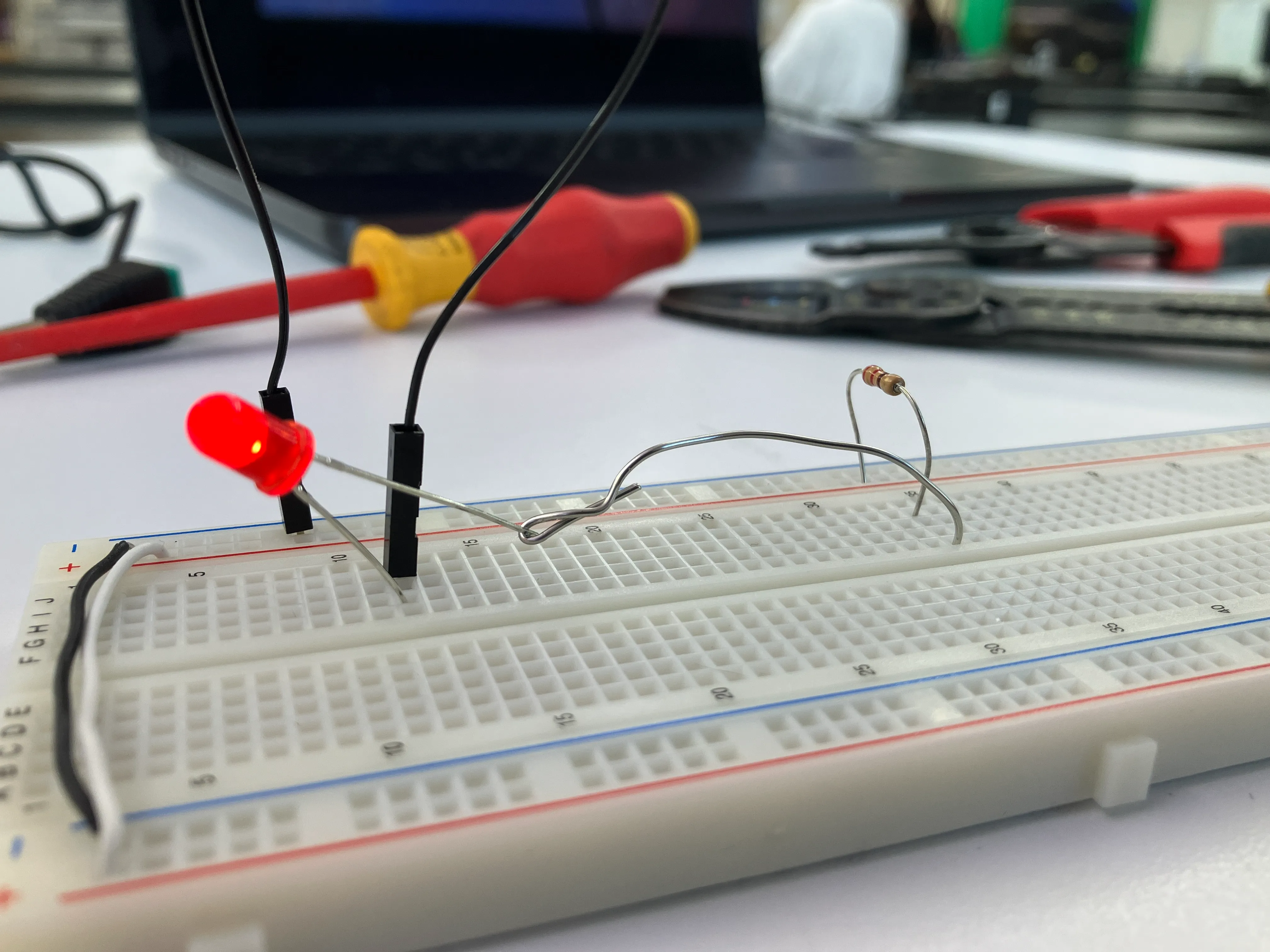
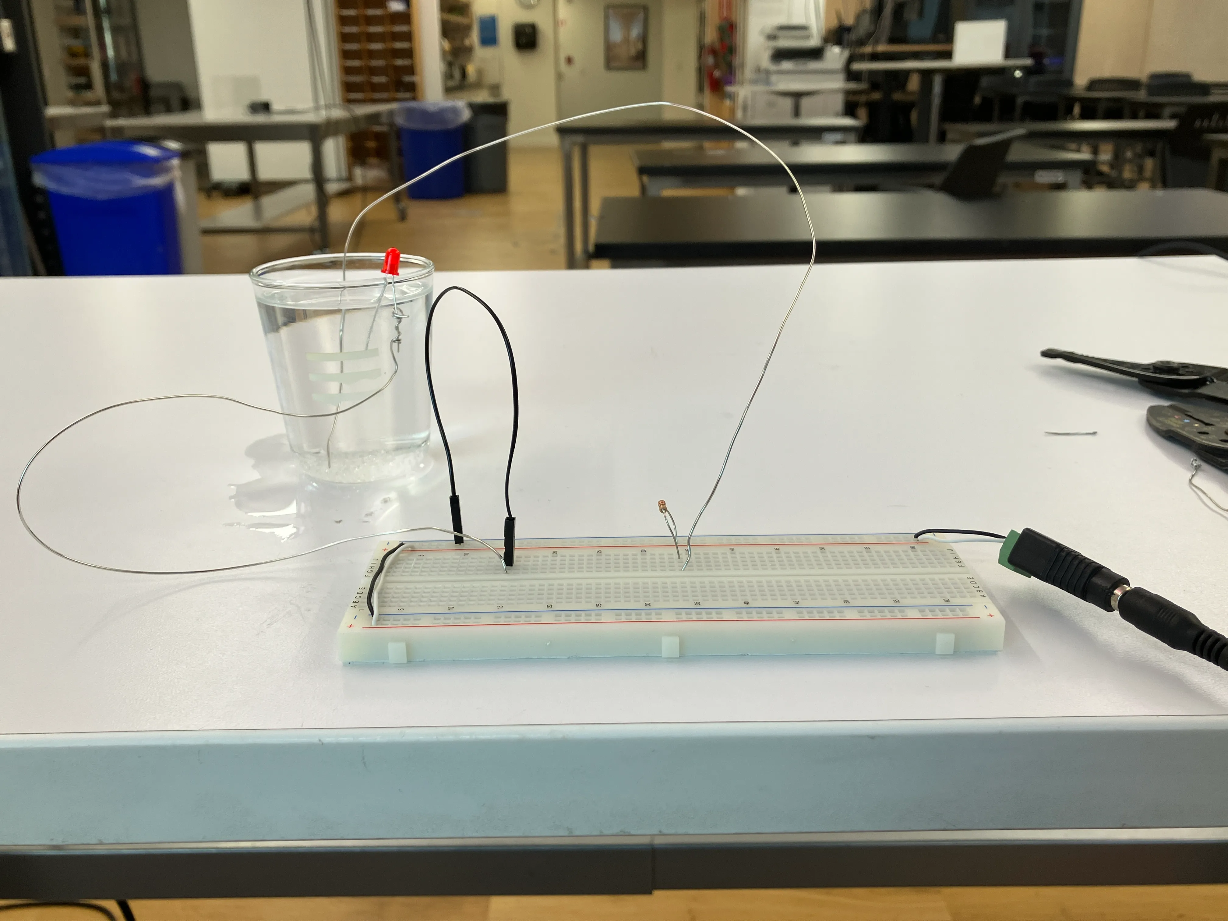
i made a floating led, because i realised that i can conduct outside the breadboard.
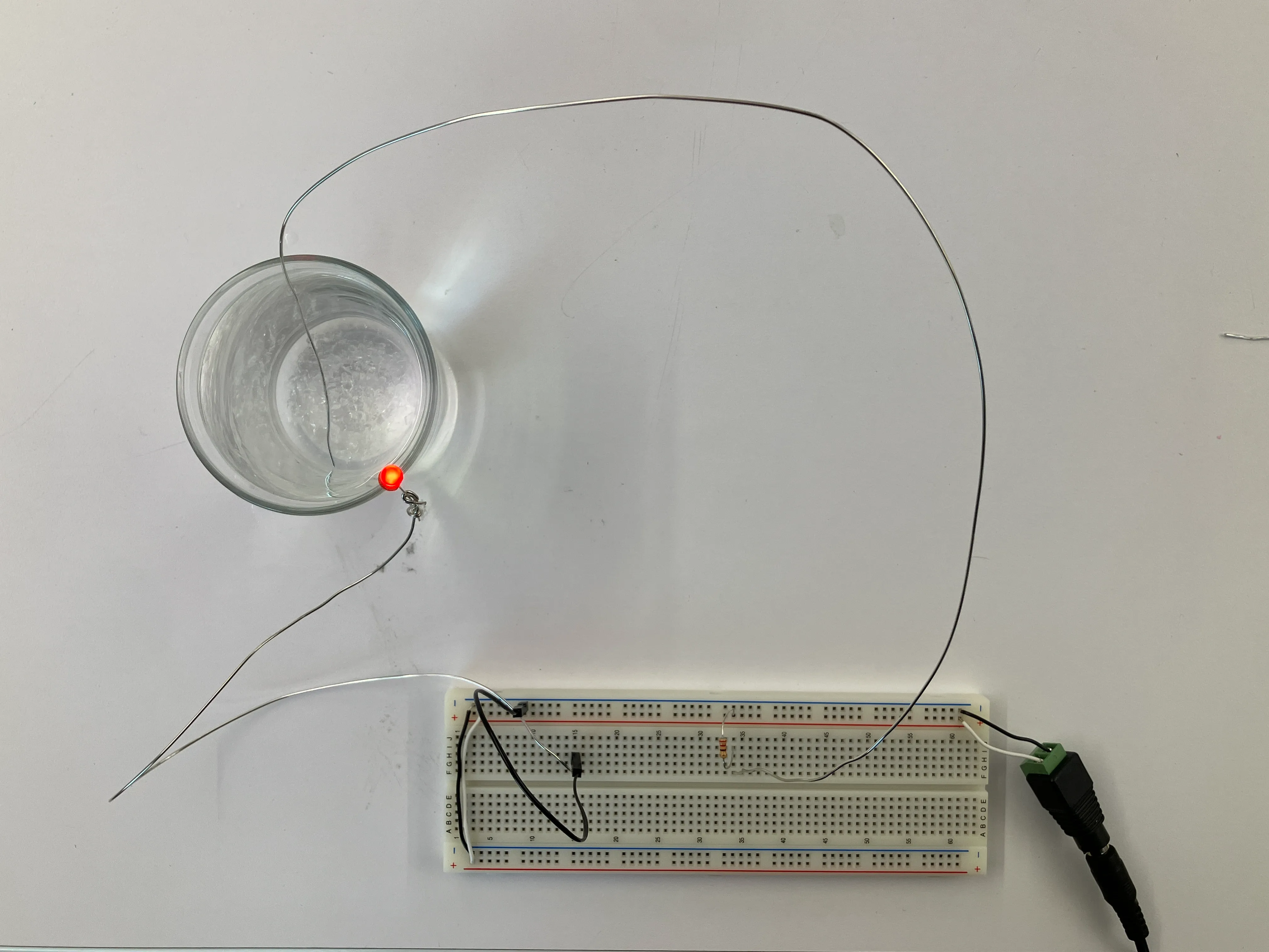
i tried conducting electricity through water, but did not succeed. i do not know why, since the electrical-circuit remains the same.
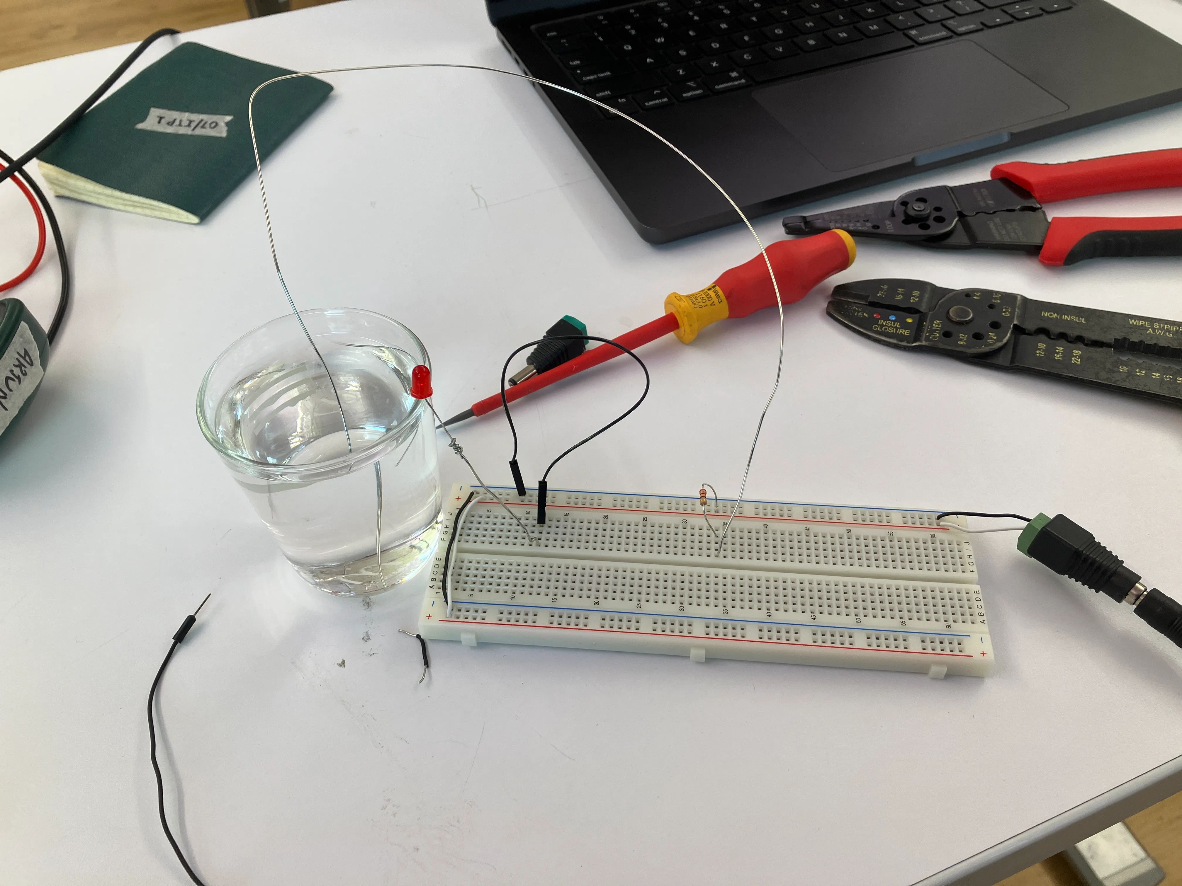
octavio made me see that the led was probably lighting, but the water wasn’t conductive enough. so, i added salt to the water to make it more conductive.
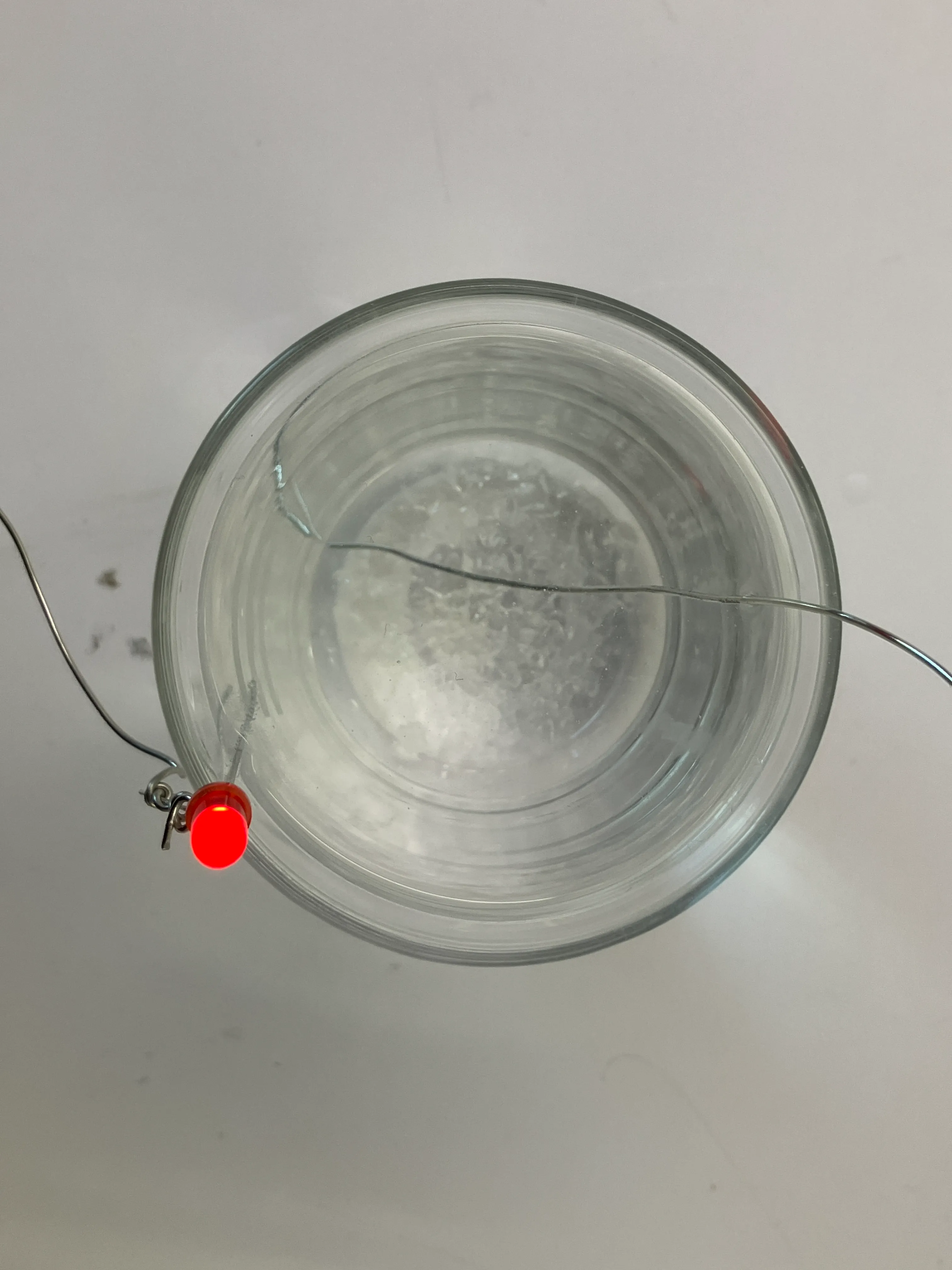
the water also made bubbles, which i thought were very cool. this is perhaps because salt & electricity are reacting in some way.
making “bad-mapping”:
have an idea that i want to execute.
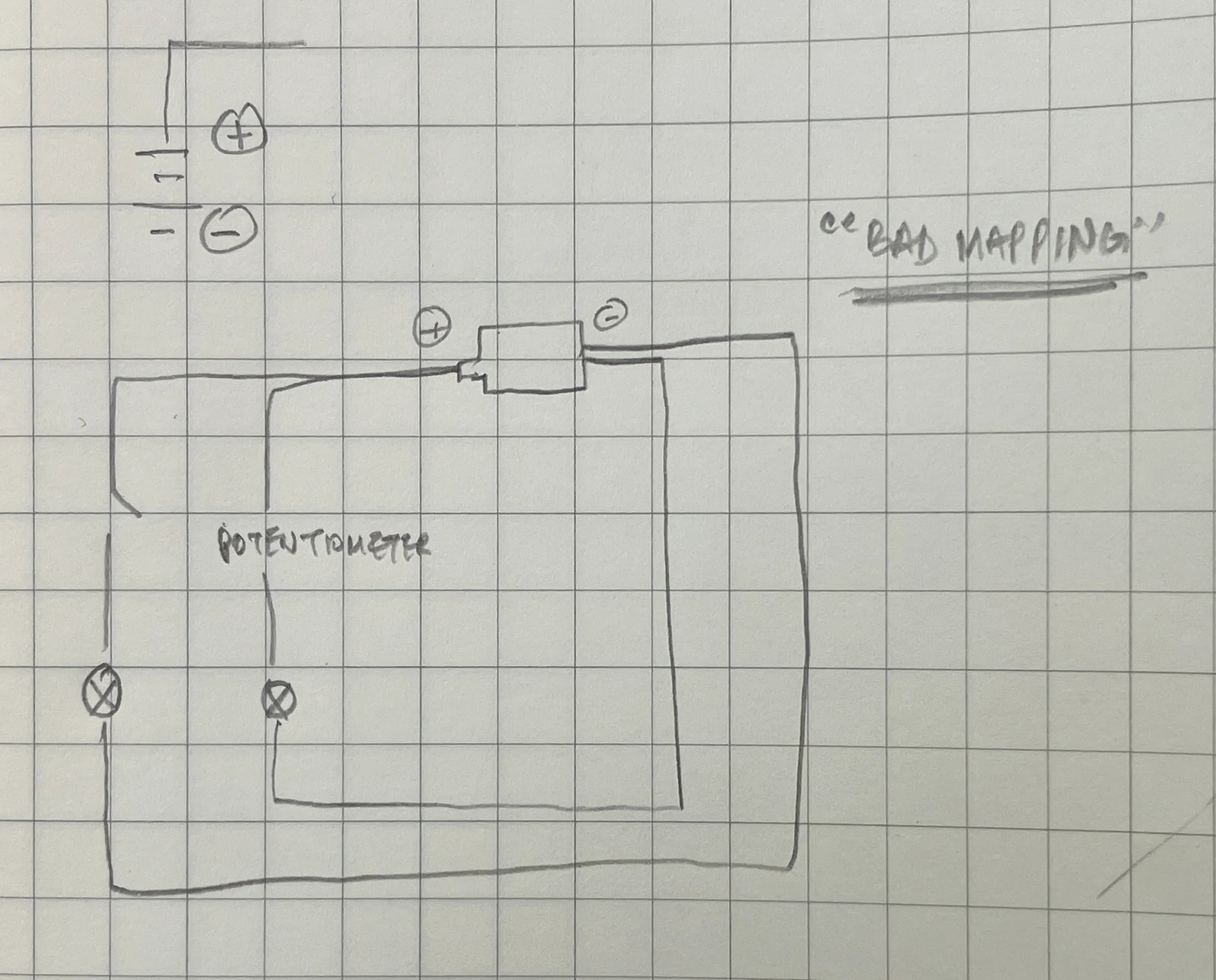
the idea is to make the led next to the potentiometer light up when the switch is pressed on, and vice-versa; as an example of bad mapping.
i want electricity to come in, and be controlled at 3.3v first. couldn’t figure out which resistor to use. learnt that; notes on electrical components.
realised that to measure current, i need to put the multimeter in series with the circuit. so, i did that.
realised that i’ve been wiring my circuit wrong all along. the power throughout the board is not controlled, and is powered straight through the dc power-supply (12v).
i’m so confused.
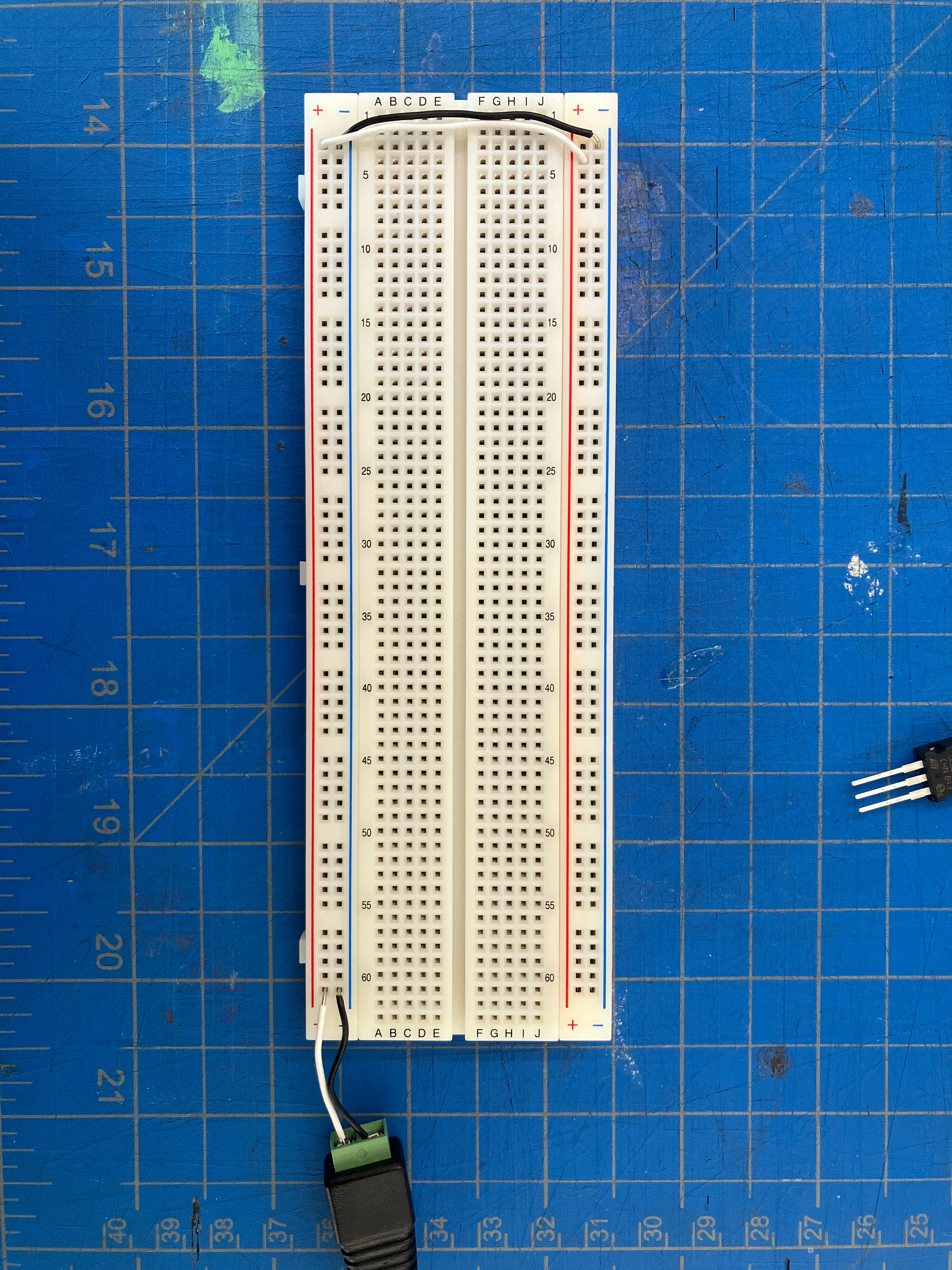
i don’t think i’m conceptually wrong, so i’m going to try again. first, i have power throughout the bus of the breadboard at 12v, because the buses are connected and power flows through them. now, these buses can become power-strips of sorts.
now i have that:
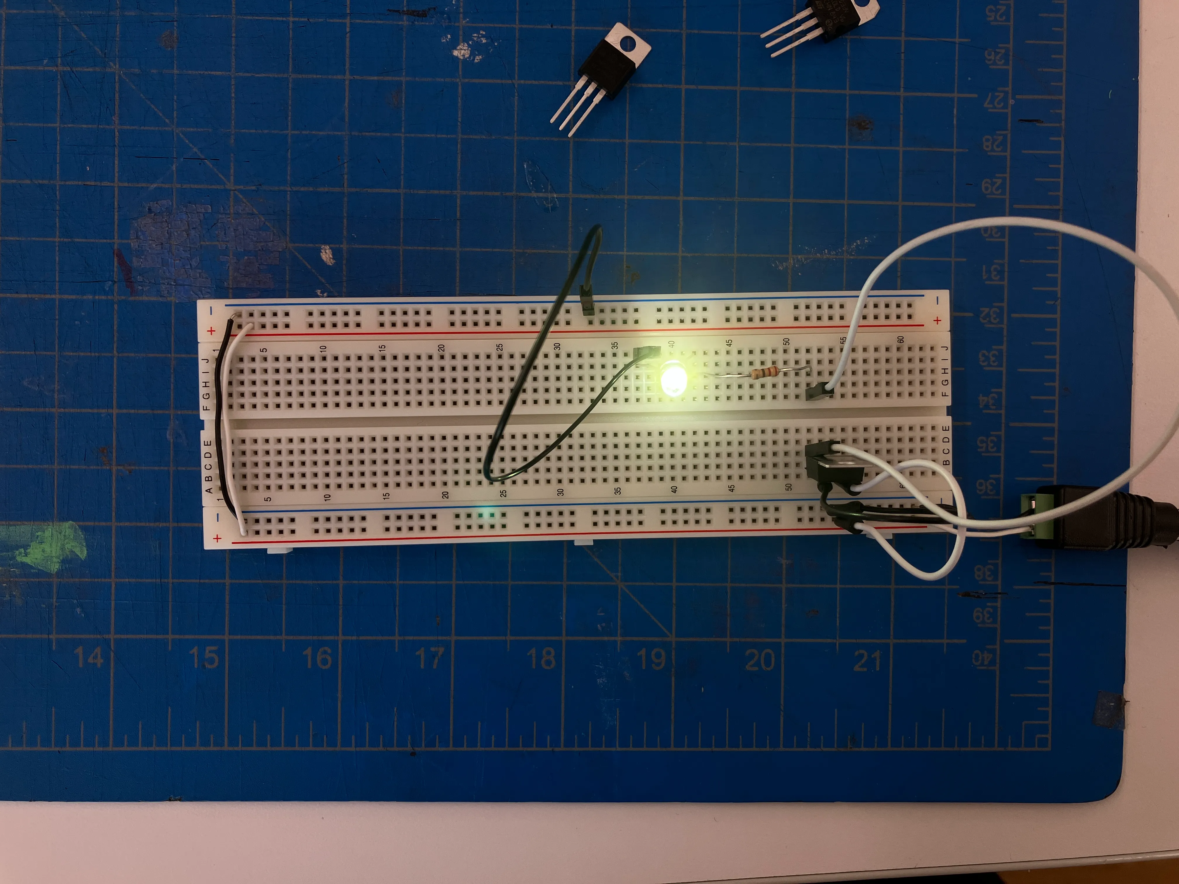
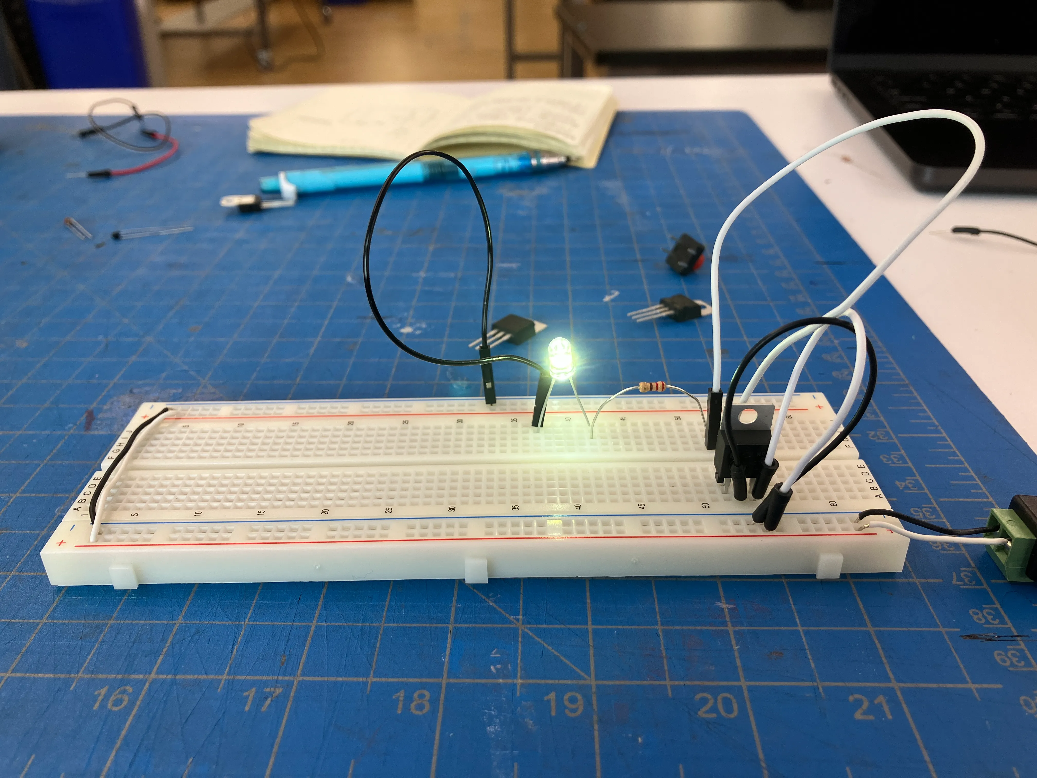
now this means, my electricity came in at 12v, got reduced to 5v, then consumed by the resistor and the led.
next, i’m going to add a switch.
for some reason, i got a reverse-switch. the circuit closes when i press it, and remains on by default.
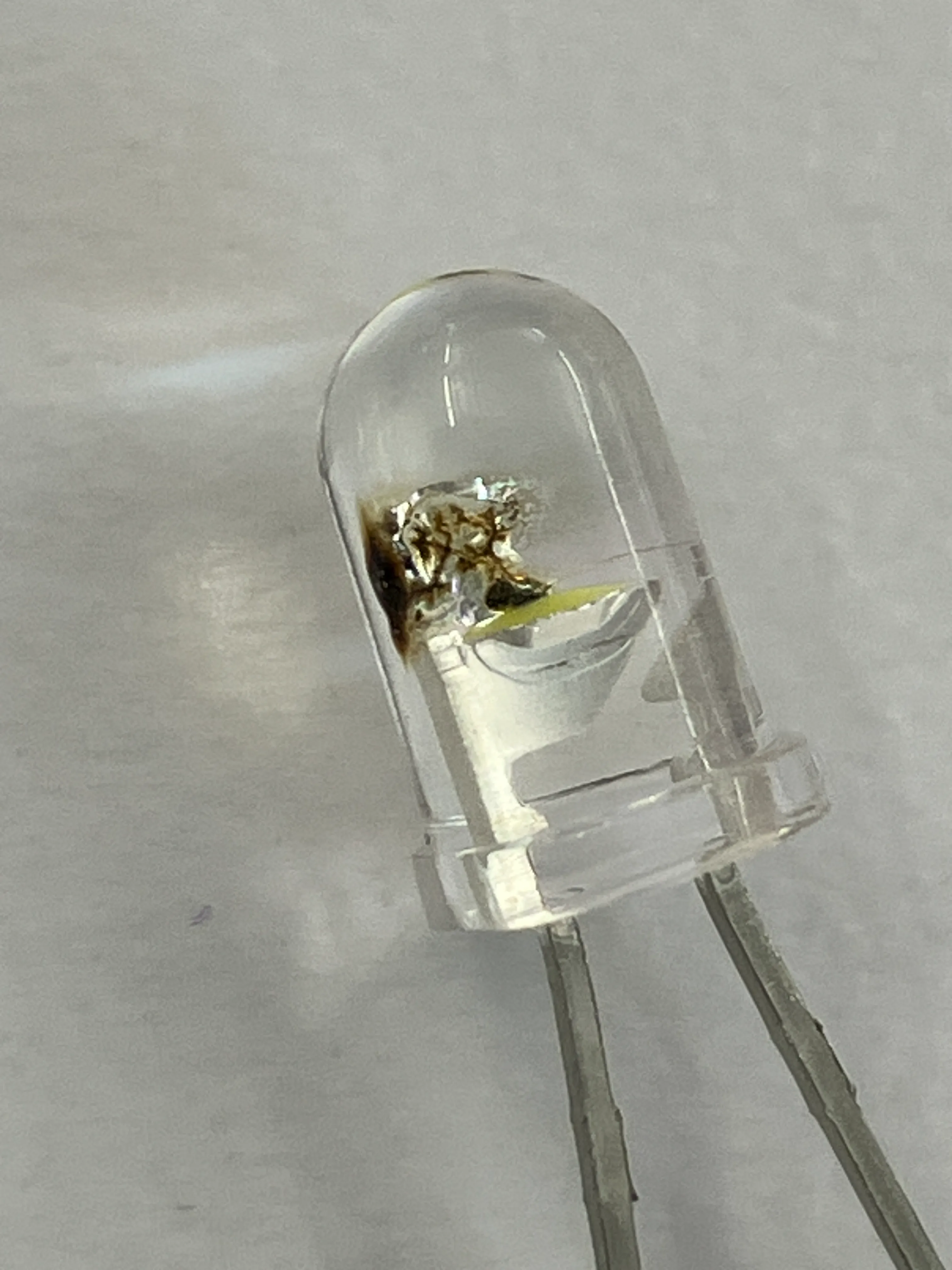
got the potentiometer to work, but burned an led.
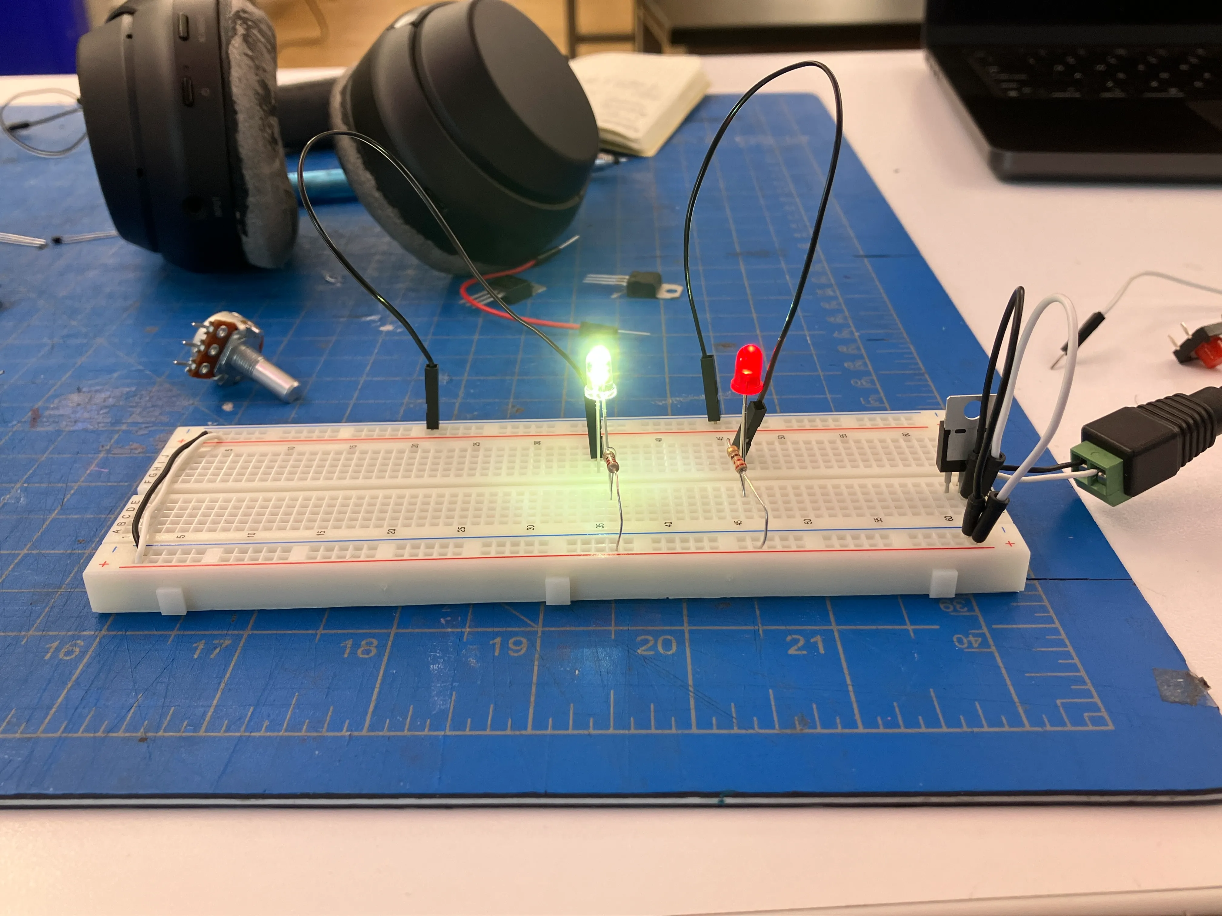
made leds light up in parallel.
moved on to making switches. i destroyed so many leds, that i felt bad, and reused the leds as my switch:
after making things, and reading (a brief rant on the future of interaction design, by bret victor & no to noui, by timo arnall (against invisible design)), i realise that displays are fundamentally arrays of leds on a screen.
we could’ve (and still could) do so much with basic electricity, controlling how different parts of a surface light up.